I am in the process of installing some Red Series On/Off (LZW30-SN) throughout the house after some disappointment with Shelly 2.5s. I haven’t had much trouble wiring up the ‘normal’ switches, but when looking at these three 3-way switches, I would love some confirmation before I jump into action. The box with two 3-ways is at the base of the stairs and controls that area, while the other set of switches is in the laundry room. The laundry room switch is mainly just for automation purposes as it controls an overhead utility light, while all of the lights controlled by the stairs are color bulbs. I’ll attach the pictures here and if any more are needed I can provide them. Any help to identify the wiring or even the diagram from the manual would be a great place for me to start and is greatly appreciated.
Also, I am planning on using the existing dumb switches unless there is some benefit/advantage to replacing the dumb switches with aux switches.
Ok, lets back way up. Are you trying to work on two separate 3-way legs, or just one that happens to be in a 2-gang box? It’s not clear from the description and the pics don’t help, so let’s start with that.
If you want to do both, we need to look at them one leg at a time or it gets confusing when dealing at it in this manner.
We’re going to start with the switch on the left in the laundry room which you labeled “Laundry Room by door”. What does this switch and the one on the other end control (so we know what to call it)?
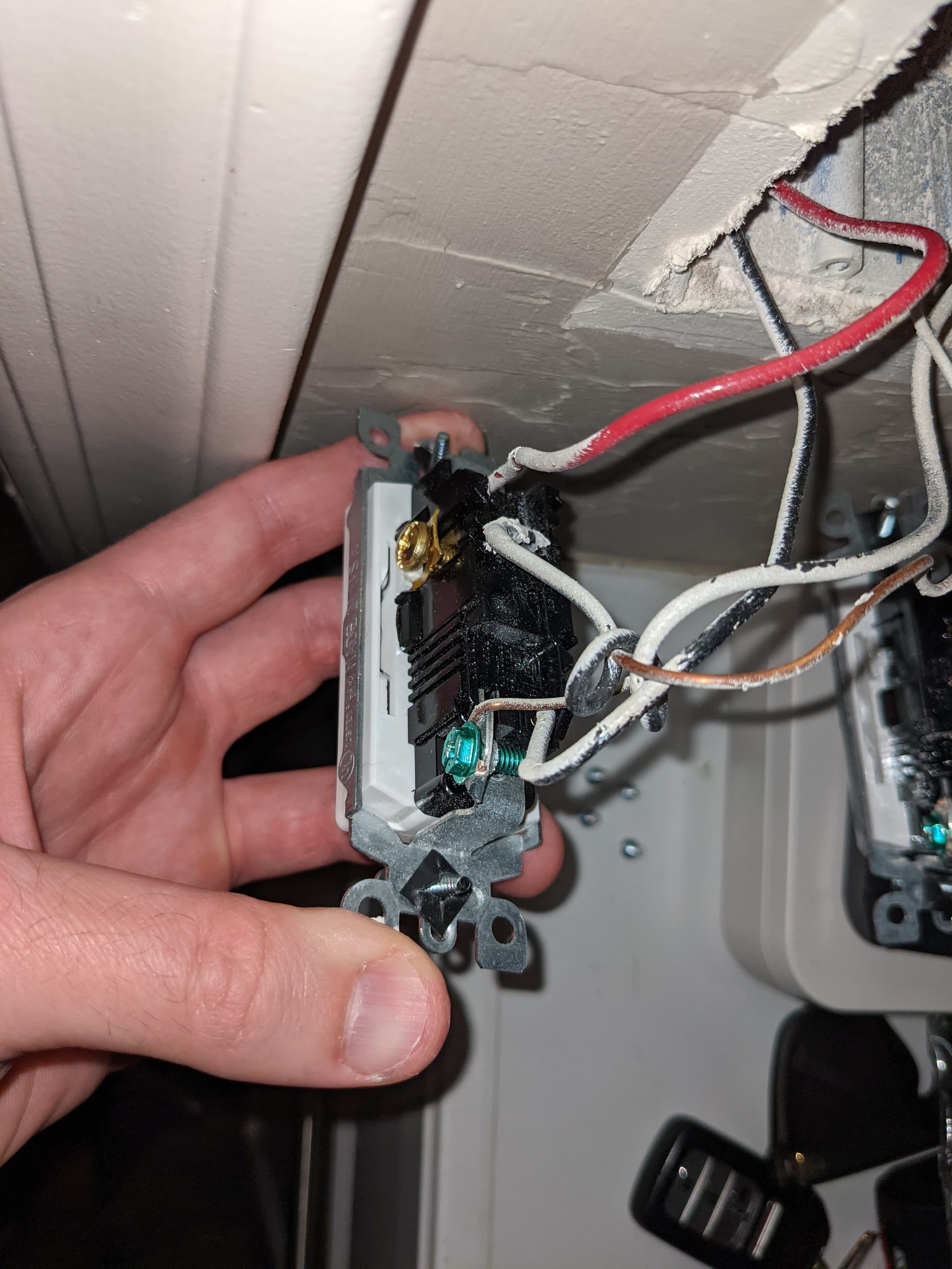
When you take pictures, you need to take them so that you can see the connections to the switch AND into the box to see the Romex coming in IN THE SAME PICTURE. TBH, a picture of a switch where you can’t see the connections, or a box where you can’t see the switch doesn’t help too much.
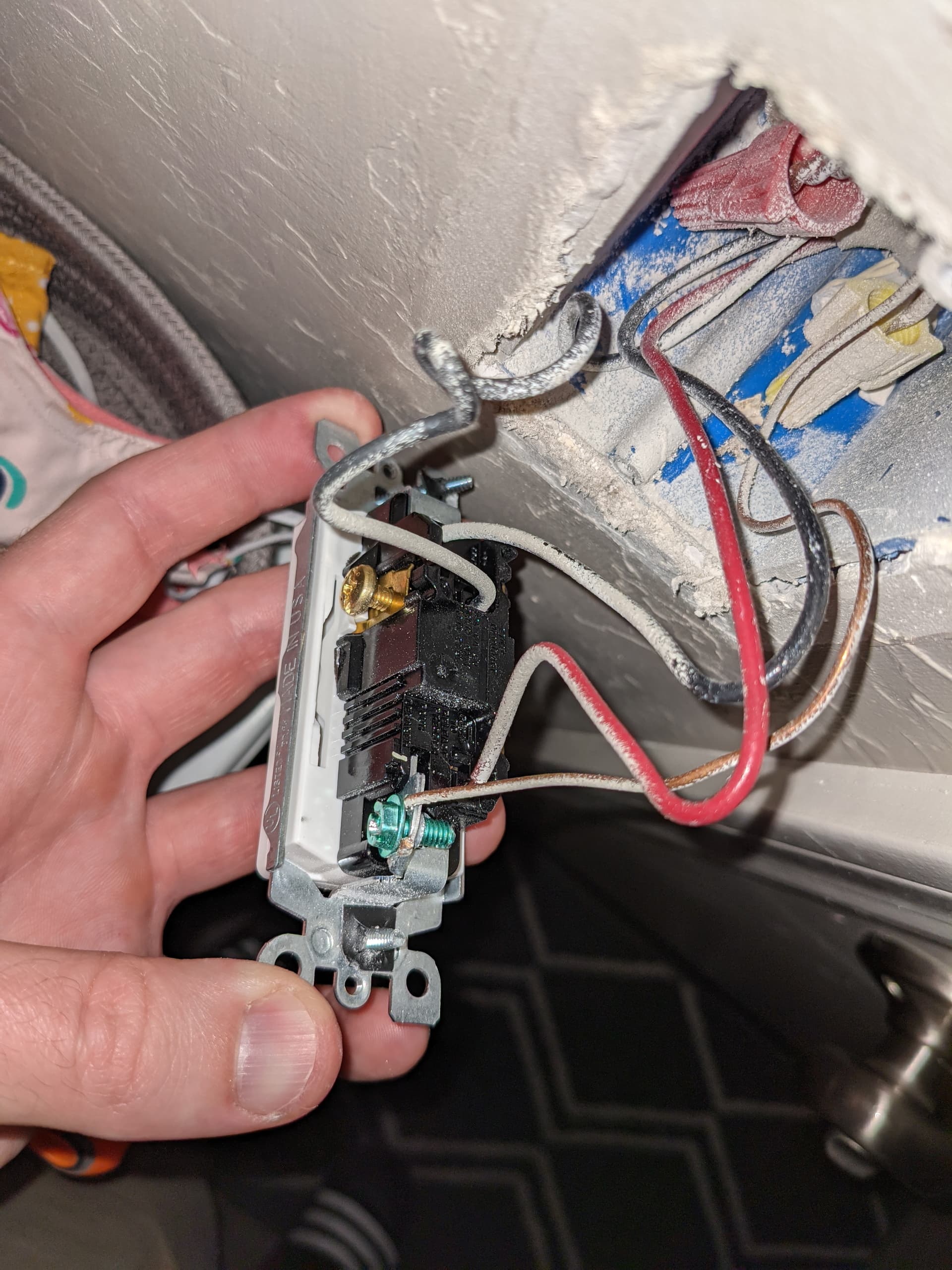
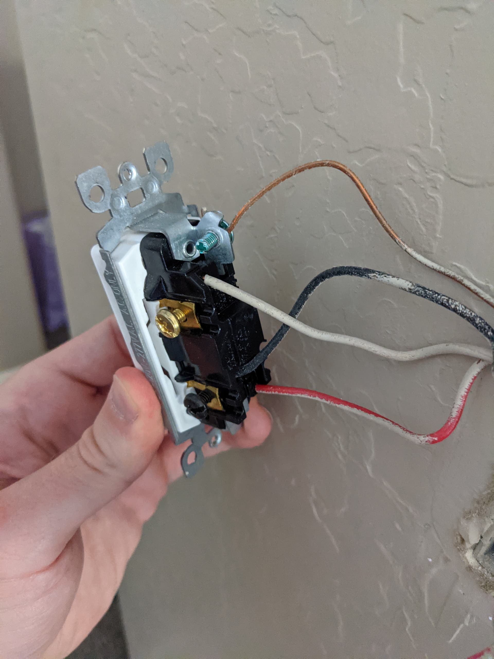
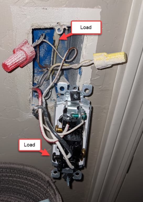
The “good” pic of the ones you posted is the first one which is in the laundry room by the door, which I’ll call Laundry Room Left. From that pic alone I can see that all three conductors connected to the switch are from the same Romex. We have to see the connections at the mate to tell for sure how this leg is wired.
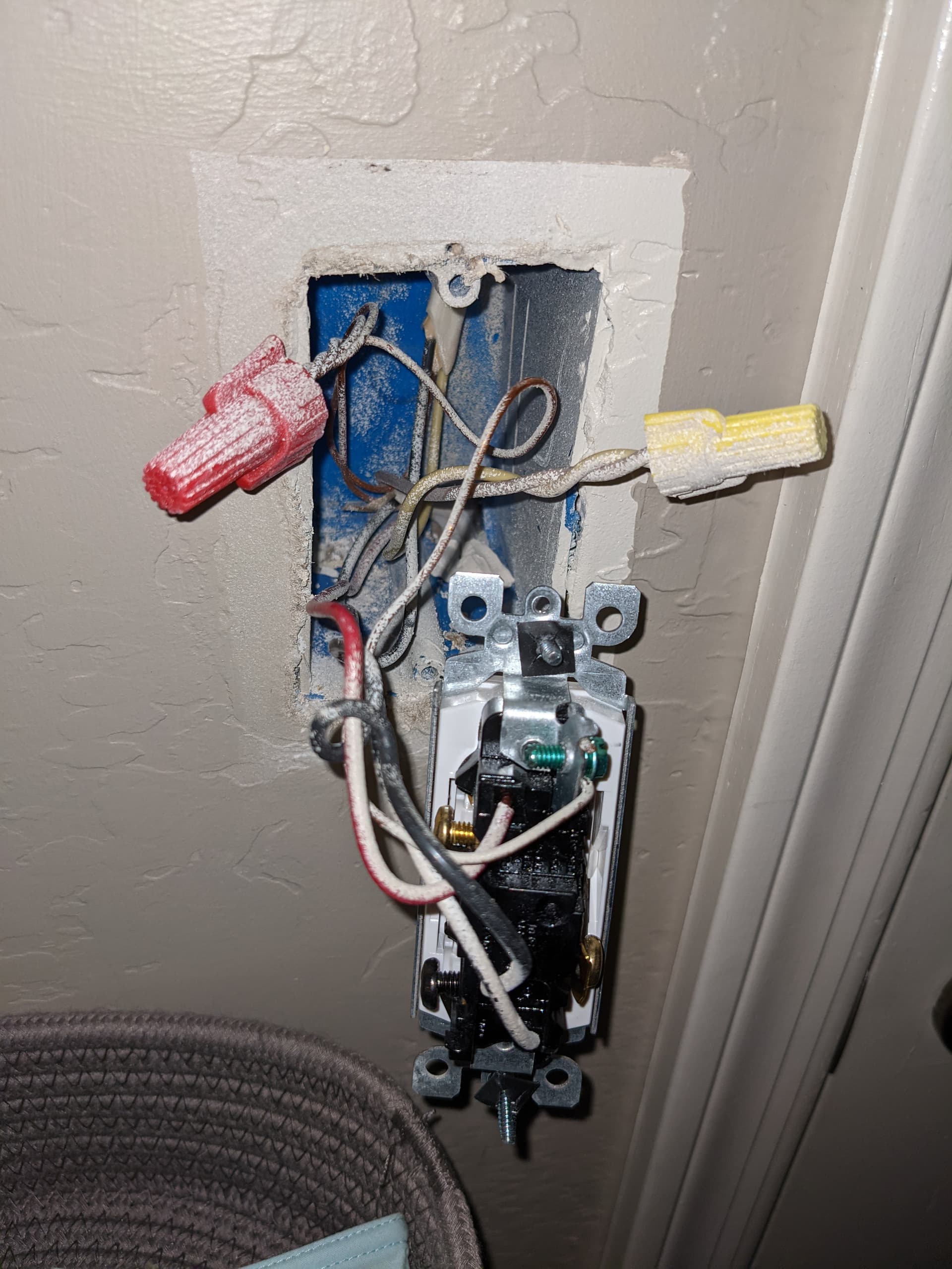
So for now, post pics of Laundry Room Left’s mate at the bottom of the stairs, and left us know what you call this leg. i.e. overhead utility light (if that’s what this one is).
Oh man. Thank you for your patience. This has been an afternoon of education. Let’s forget that earlier post ever happened.
I have multiple sets of 3-way switches in the house. The laundry room is its own entity. We’ll forget about the stairs for now. Here are some better pictures.
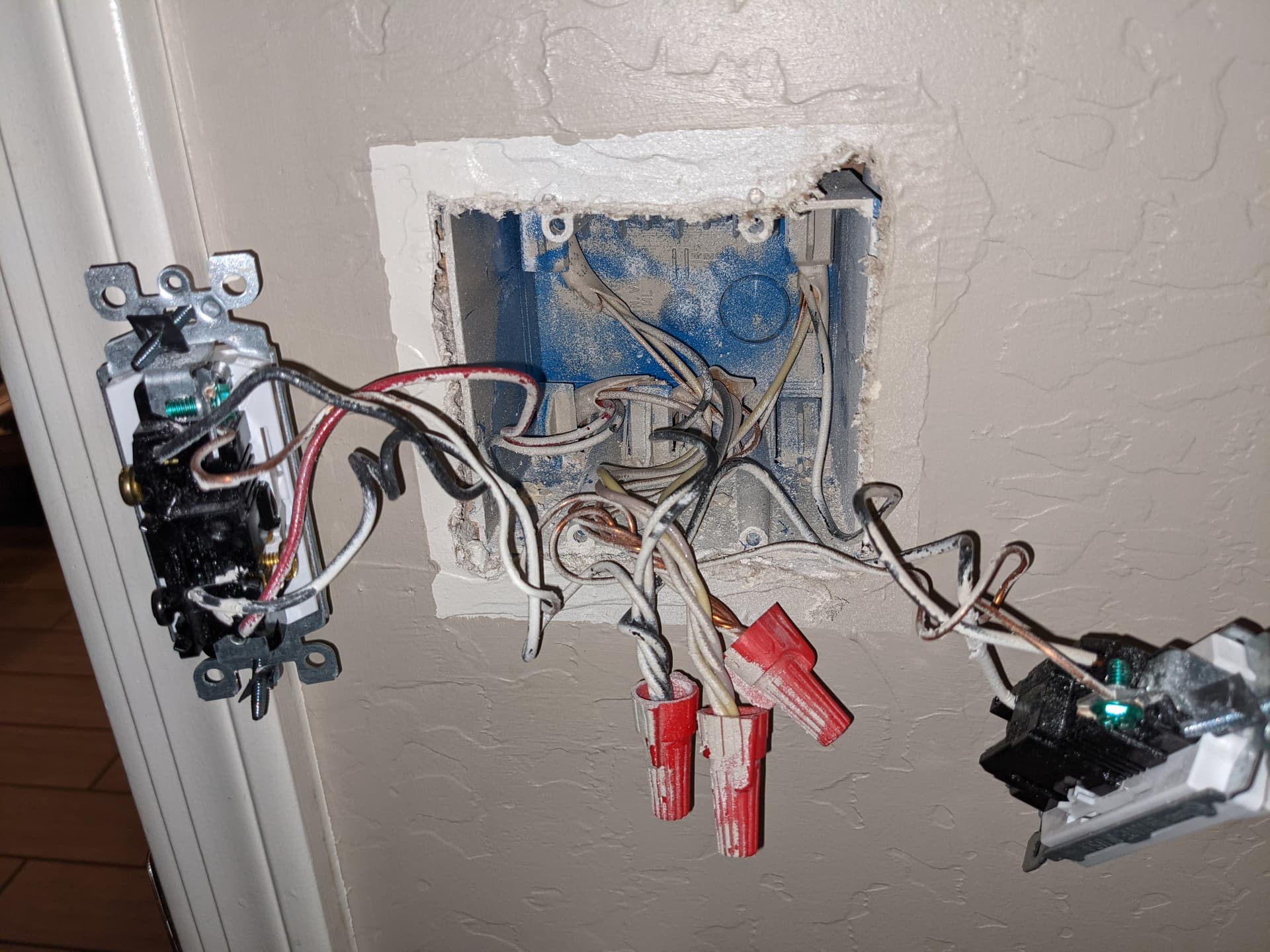
The set of two switches is on the left when looking at the room. One switch in this group controls the utility light, the other controls the exhaust fan. The single switch is on the right and also controls the utility light.
Ok, so just to confirm, we’re now working on the utility room light, which is controlled by two switches. One of those switches is in the single-gang box, the other is the switch on the LEFT in the 2-gang box. Good so far?
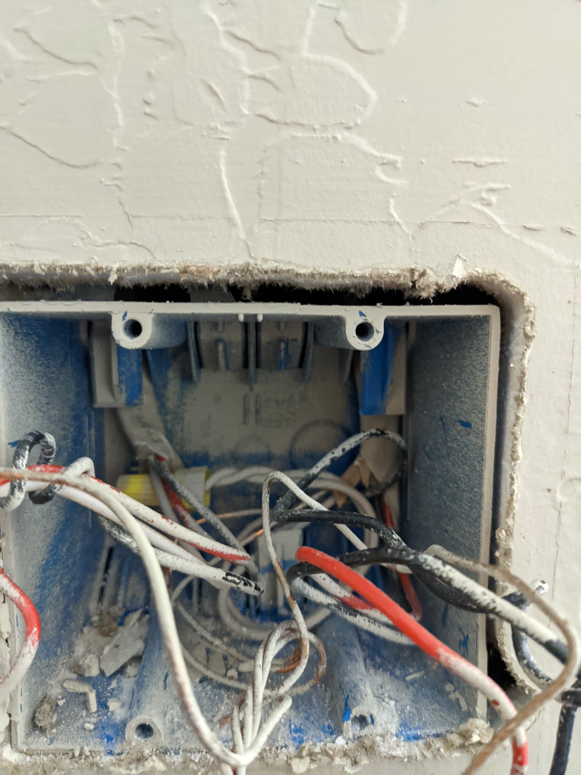
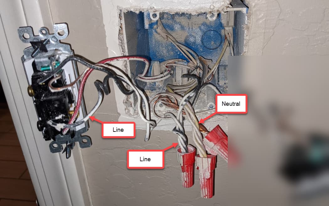
So what this appears to be is a Line and Load in separate boxes. It looks like power is being fed at the 2-gang box. What you will need to do to confirm is in the 2-gang box, remove the black conductor attached to the black screw so it’s no longer attached to the switch. USING A METER, test between that black conductor and the white bundle. You should get a constant 120VAC (or something close). Just to be thorough, test with the switches in various positions. That should not matter, as you should have a constant 120VAC.
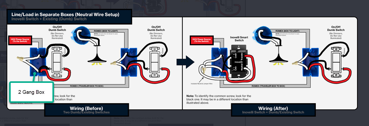
If that is the case, then your power (Line) is being fed from the black bundle in the 2-gang box. The Load to the light(s) is the black of the 2-wire in the single gang box.
So the Inovelli will go in the 2-gang box. Use the following diagram. (And while the switches are out, run the screws down into the switch bodies. Thx)
Everything went exactly as you had predicted. Everything is installed and functioning perfectly as a 3-way switch. I have quite a few single switches I’m replacing over the next few days, but when I tackle the other sets of 3-ways I have I’ll know where to start. I’ll definitely be back.
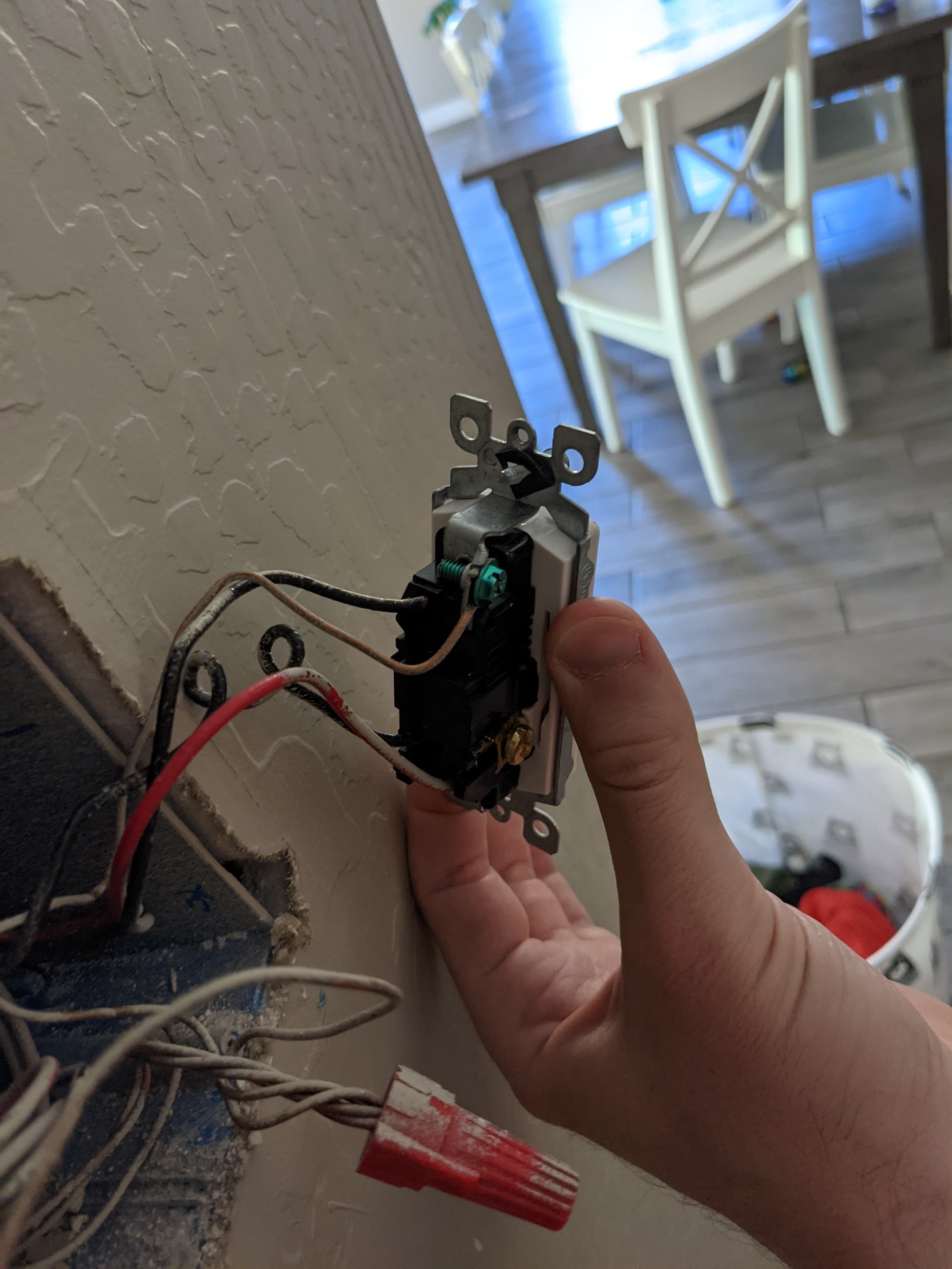
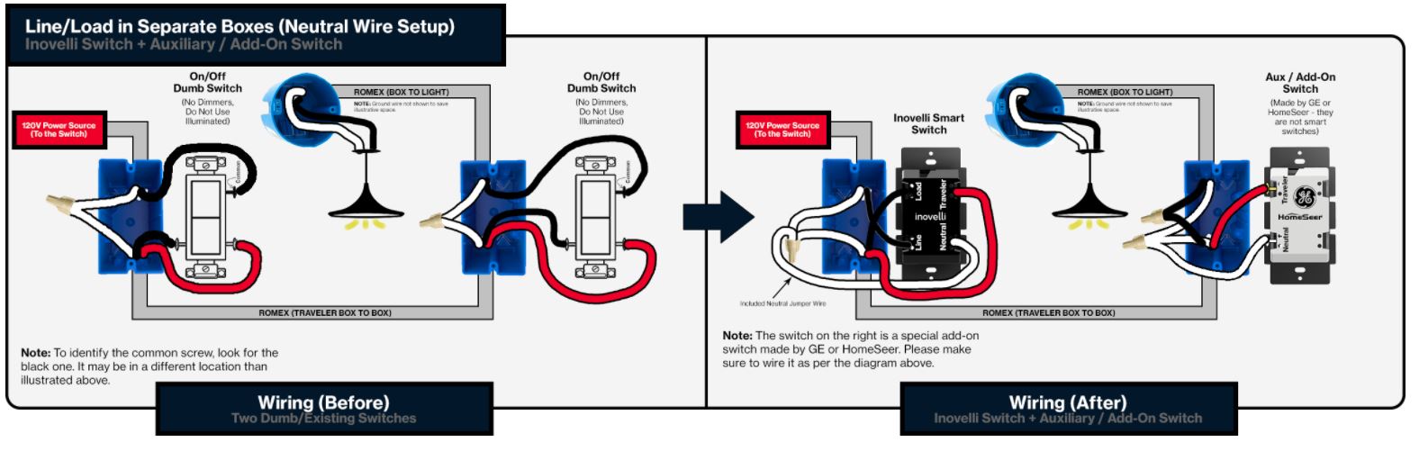
Hello again! I’ve decided that I want to update the dumb end, but I’m having trouble finding the correct GE switch spoken about on the forums. I’m seeing this one but when I am looking at the wiring diagrams vs the switch that it’s replacing, the wiring will be a bit different. I’m assuming this diagram will be what I follow:
And this will mean that I use the ground, and the red traveler wire from the original switch, add a neutral to the bundle, and then I connect the other two wires that are currently connected to the dumb switch. Right? Thanks again!
I think that model number is compatible but I am not in a position to check it right now.
You have a three wire in between your two switches. Just as the diagram indicates, you will send the load and traveler from the Inovelli to the other switch over the black and red. The white will connect to the neutral bundle.
At the aux switch, the black gets connected to the black load going to the light. The red goes to the traveler terminal of the aux.
The aux also needs a neutral so pigtail they white bundle to neutral terminal of the aux.