Would I just pigtail each wire from the aeotec bypass into the 2 wire connectors?
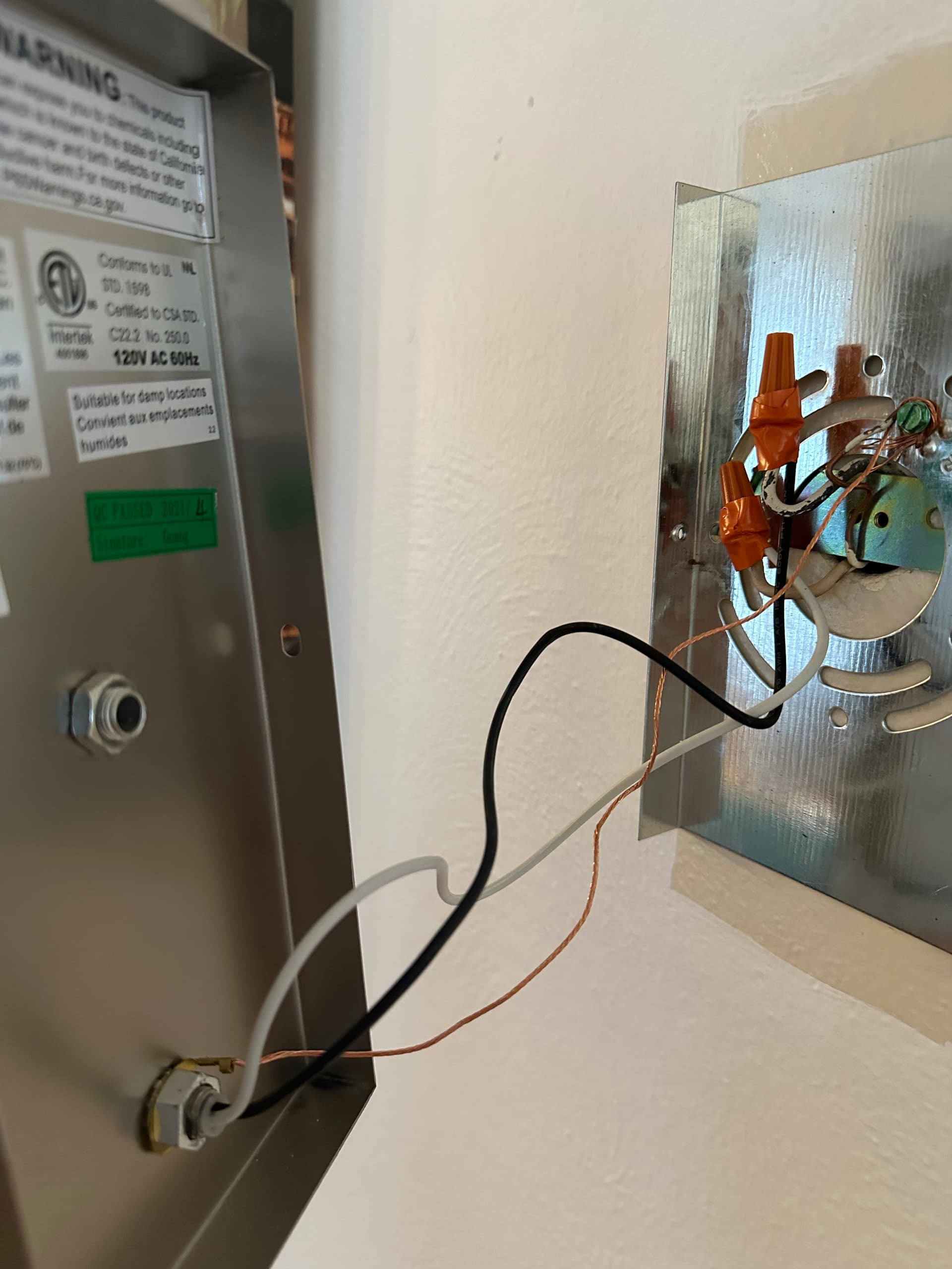
This light fixture has a neutral. The light would not work if it didn’t have one.
If you need to install a bypass because the light switch does not have a bypass, then yes just connect the one wire to the black wire nut and the other wire to the white wire nut. Make sure you have a good connection/twist under the wire nut.
Okay, yes there is no neutral at the switch. Lights flicker when dimmed and blue series switch loses power when I turn the lights off.
So I installed the bypass like you said in the picture and it is allowing me to dim the lights further than it used to without it flickering. However, if I turn the bulbs off I think the switch turns off and the up/down tap controls do not work. I turn the bulbs back on in the Hue app, they flicker on, and the switch works again.
Does it matter which wire from the aotec bypass I attached to black/white in the fixture?
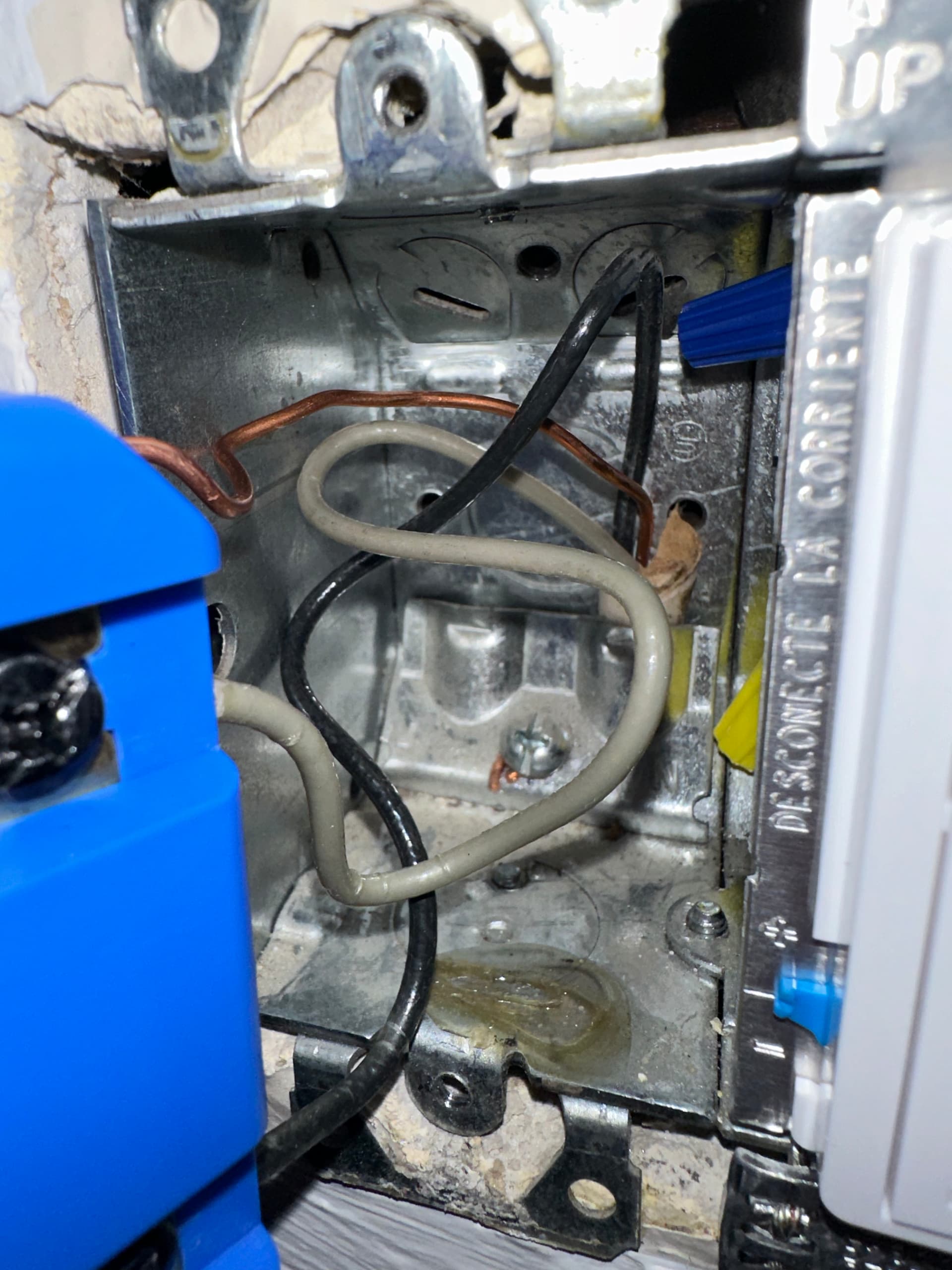
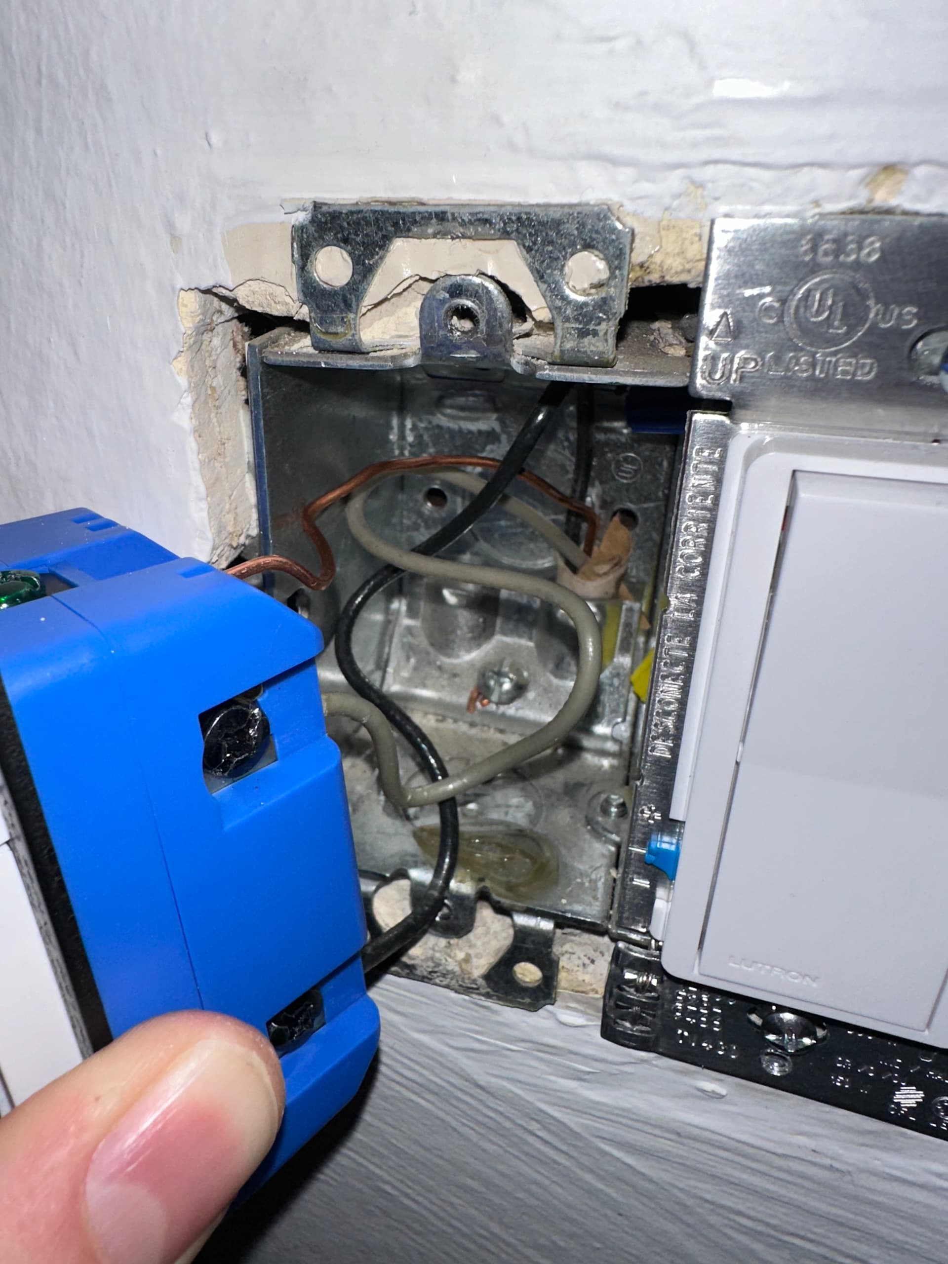
You’ve mentioned a couple times that your Blue switch is losing power, so it sounds like something may be awry with how it’s wired… Can you show a picture of it pulled out from its box so we can see how it’s wired and what the wiring looks like in the box itself? That may require multiple pictures.
Also, does just that one Blue control this fixture, or is it part of a multiway switch setup?
ETA - it doesn’t matter which wire on the Aeotec bypass connects to live or neutral.
How many lights are on this switch leg? If it is just one I am inclined to agree with @hydro311. The picture of the light fixture that you posted is wired as a neutral switch leg.
So unless there are more lights that are controlled by the switch, you do not have a non-neutral installation. If there are more lights controlled by the switch, then you placed the bypass at the incorrect light.
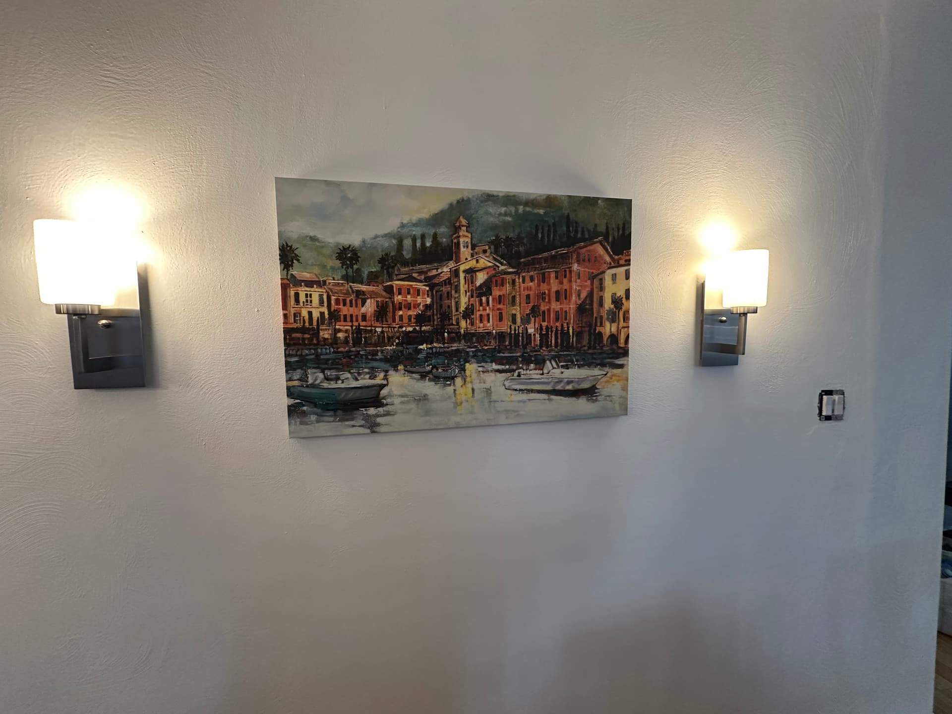
It is a single pole switch that controls 2 light fixtures. The one pictured and another fixture that is the same. Both have the Hue A19 - E26 smart bulb - 60W.
I will post a picture of the wiring to the switch tomorrow.
There are no neutrals in the light switch box.
I attached the bypass to the light fixture closest to the switch as I thought I read that is the proper way to do it. I can try it on the other one to see if that works.
Here are 2 pictures of the wiring to the switch. The Lutron switch on the right is on a different circuit and controls different lights. The 3rd picture is the bypass now attached to the fixture on the left (previously was on the right). 4th picture is the 2 fixtures and the switch.
I was still having the same problems after switching the bypass from the right fixture to the left fixture. When I turn the bulbs on they flicker for a second and then remain on. The LED on the switch goes from blue to pink to green (sometimes it went from cyan to blue to green).
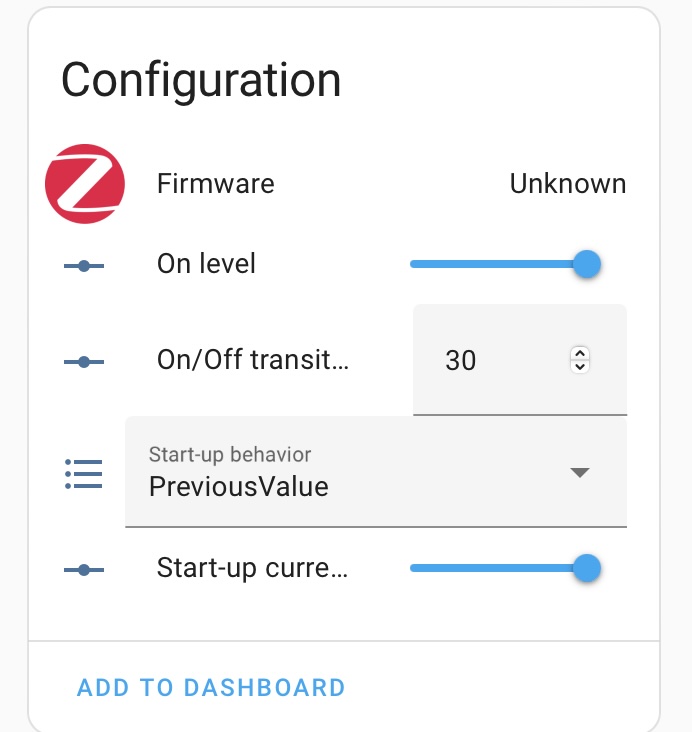
So I just factory reset the switch and then excluded the switch and then added it back in to HA. It is now functioning like a normal light switch and seems to keep power when the light is off (the blue LED stays dimly illuminated). However, I can no longer see the configurations in the HA device settings and I am unable to(/unsure of how to) put it back into “smart bulb mode.”
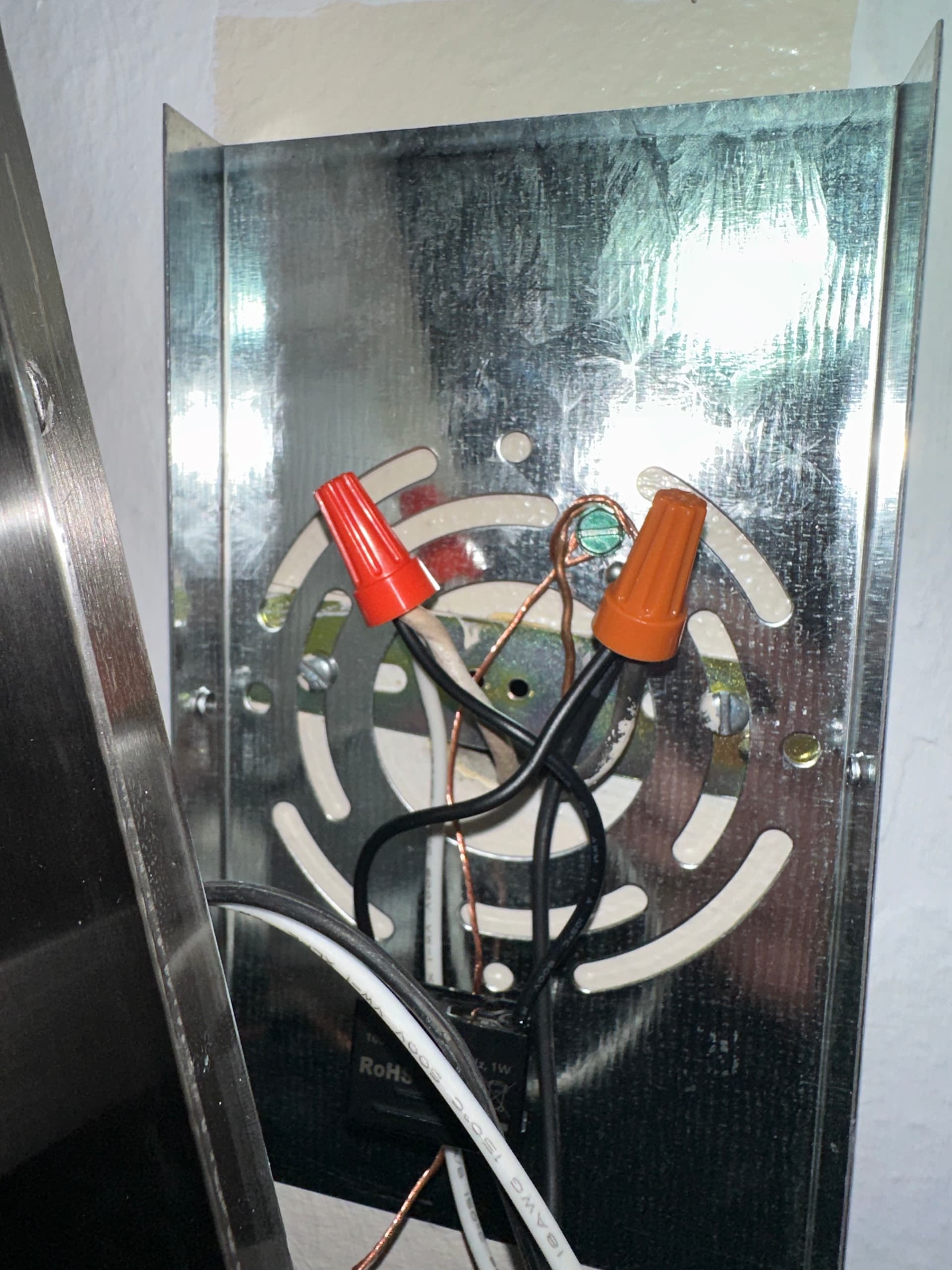
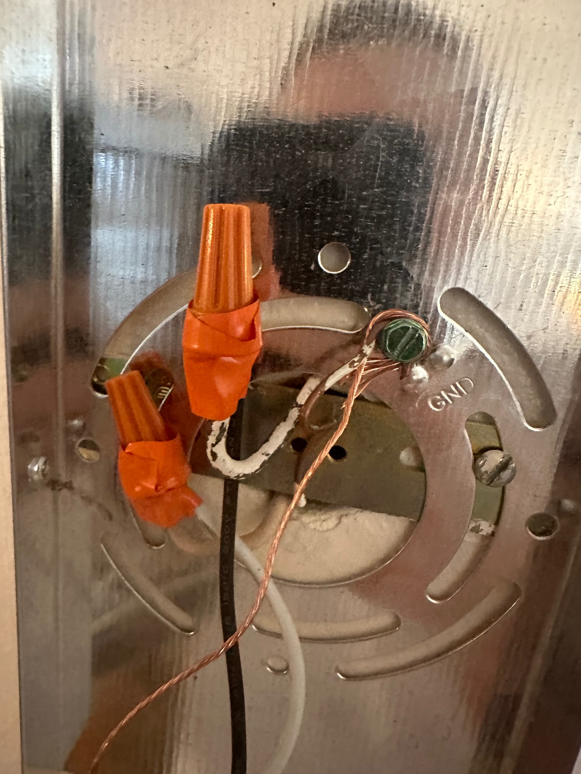
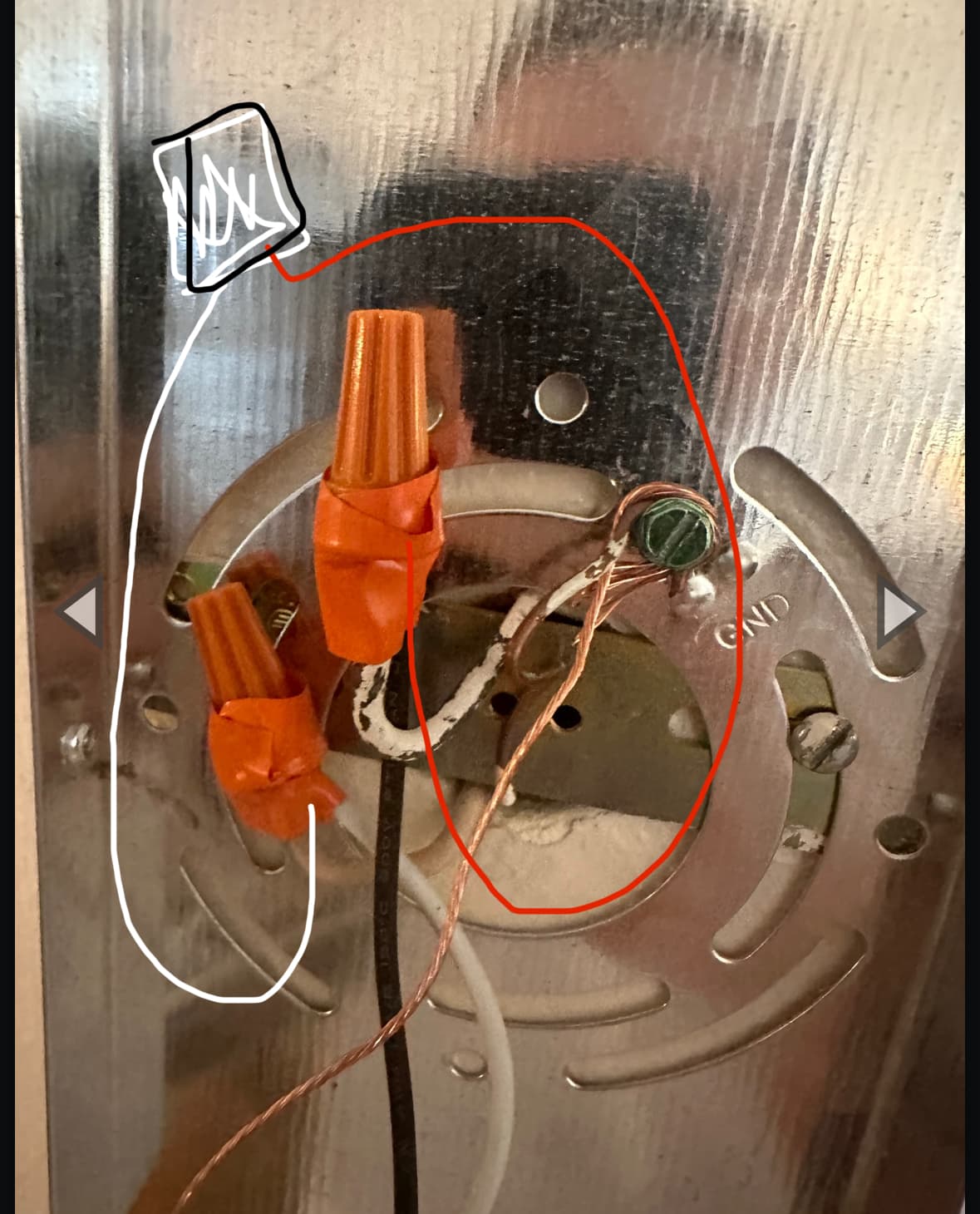
I’m curious to know if the line voltage is coming down on black or white wire. Can you take a photo of the wiring behind the other light?
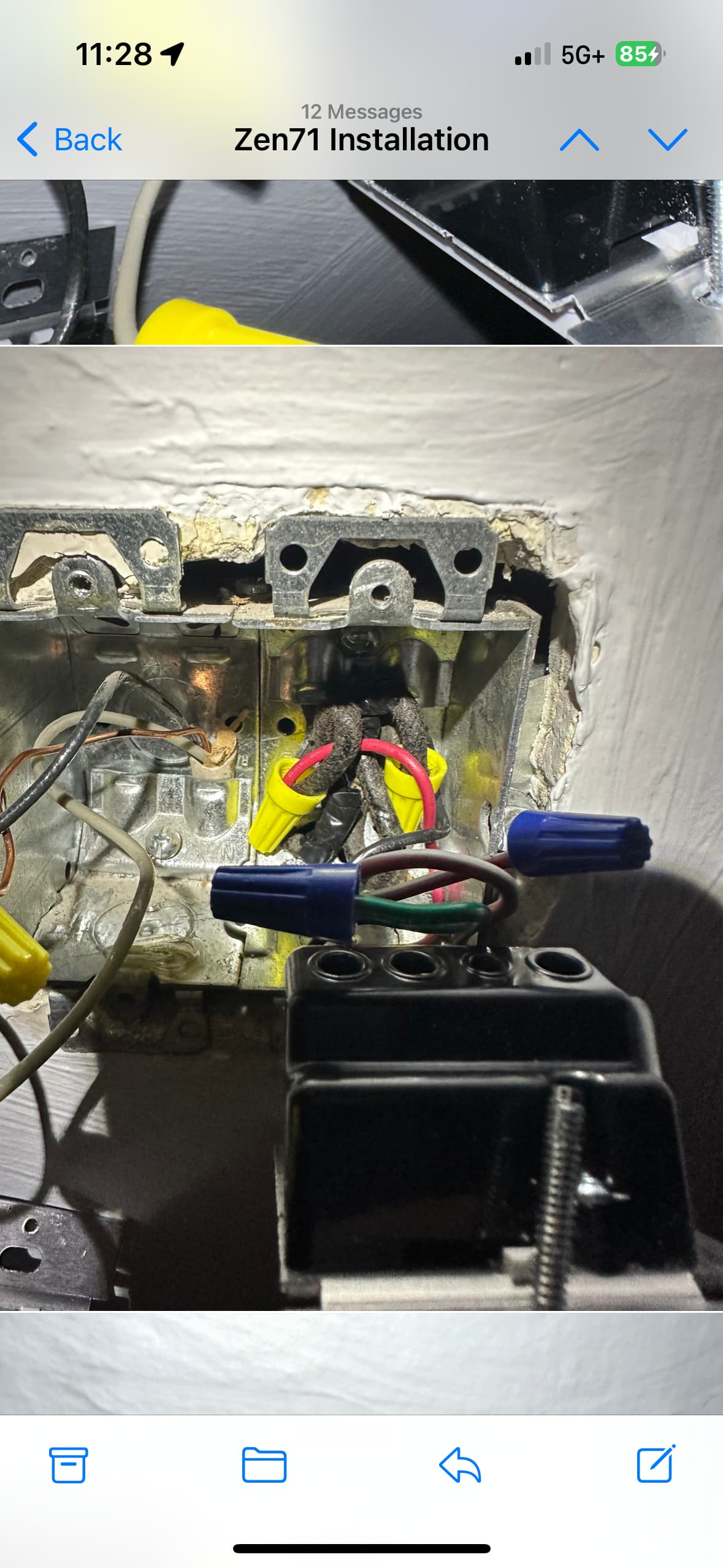
I understand @harjms confusion. In a non-neutral, power comes into one of the lights. At the light there should be 3 PAIRS of conductors (excluding the ground):
- Incoming power
- Connection to the light
- Connection to the switch
I’m only seeing two pairs in each of your photos, which suggests to me a hidden junction box. So we’ll disregard the lights for now . . .
At the switch, how did you determine which conductor was the hot? Did you test? If so, how?
Voltage tester. Switch should be wired correctly. Would adding a 2nd bypass help so there is 1 on each fixture?
When you tested at the switch, did you test between each conductor and the ground? The reason I’m asking is that the common convention for wiring a non-neutral is to send the hot to the switch over the WHITE and return the switched hot over the black. Of course, there is no guarantee yours is wired that way.
That’s why we wanted to see how the hot was sent to the switch, but your pictures don’t show that. So double-check your connections at the switch, because if your HOT is the white as is the norm, then you have the conductors reversed at the switch.
Yes, you can try a 2nd bypass wired parallel to the first one at the same location. That has solved issues for some where one bypass alone did not work.
Just rechecked. Disconnected the switch then used a non contact voltage tester. The black wire had power and the white wire did not.
I am confused as to what my pictures do not show. Where else should I take a pic?
2nd bypass arrives today. You are saying I should connect it at the same place the other one is connected instead of having one bypass on each fixture?
Thanks again for your help.
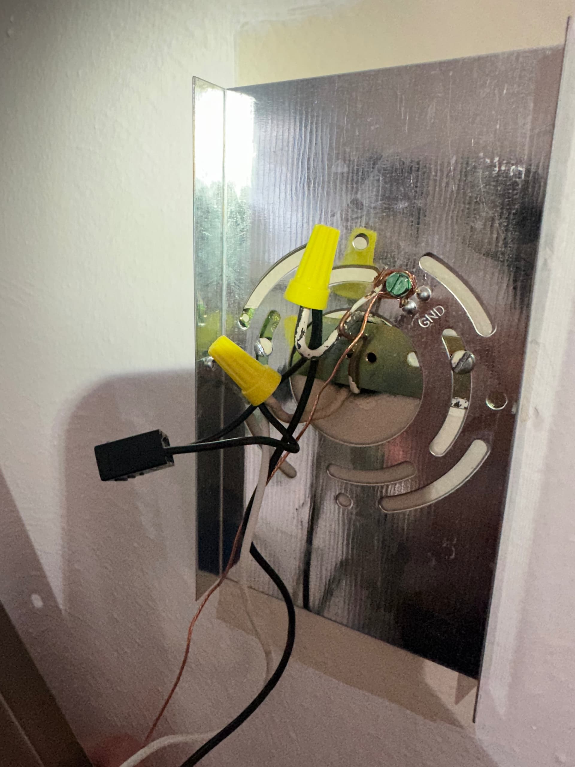
I’m looking for where the incoming hot at the light goes to the switch. There should be 3 pairs of conductors at that box, the incoming hot/neutral, the pair to the light and the pair to the switch. Your pictures only show two pairs at each light box. That is why I made the comment above about the missing junction box.
Plus, one of your lights should have an extra pair going to the other light. I don’t see that either. I suspect the hot comes into a junction box somewhere and then then lights are fed. This doesn’t really mean much in the scheme of things other than we were trying to see how the hot was fed to the switch to double-check. But since you have confirmed the hot is on the black, there is no need to hash this out further.
Yes. AFAIK, everyone that has solved the issue has doubled up at the same light. Don’t reallly know if it makes a difference, but everyone I’ve corresponded with here has doubled up.
Should I put both of the bypass’s on the right fixture (closest to the switch) or the left (farther from the switch)? Or does it not matter?
Put it closest to the switch, although I don’t know for sure if it matters. In your case, use proximity to determine closest. In reality, however, since there is likely a junction box somewhere, you really don’t know where closest is. So try it at the physically closest, and if that doesn’t work, try it on the other.
Tried it with 2 of them on the right fixture, 2 on the left fixture, and then 1 on each fixture with no luck. Going to return the switch at this point. I’ve put way too much time into this. Thanks for your assistance though and taking them time to help me try to figure this out!