I’m stumped. I’ve wired up dozens of smart switches but I can’t sort out this one. It is in an older part of the house (1960s) so it may not have neural.
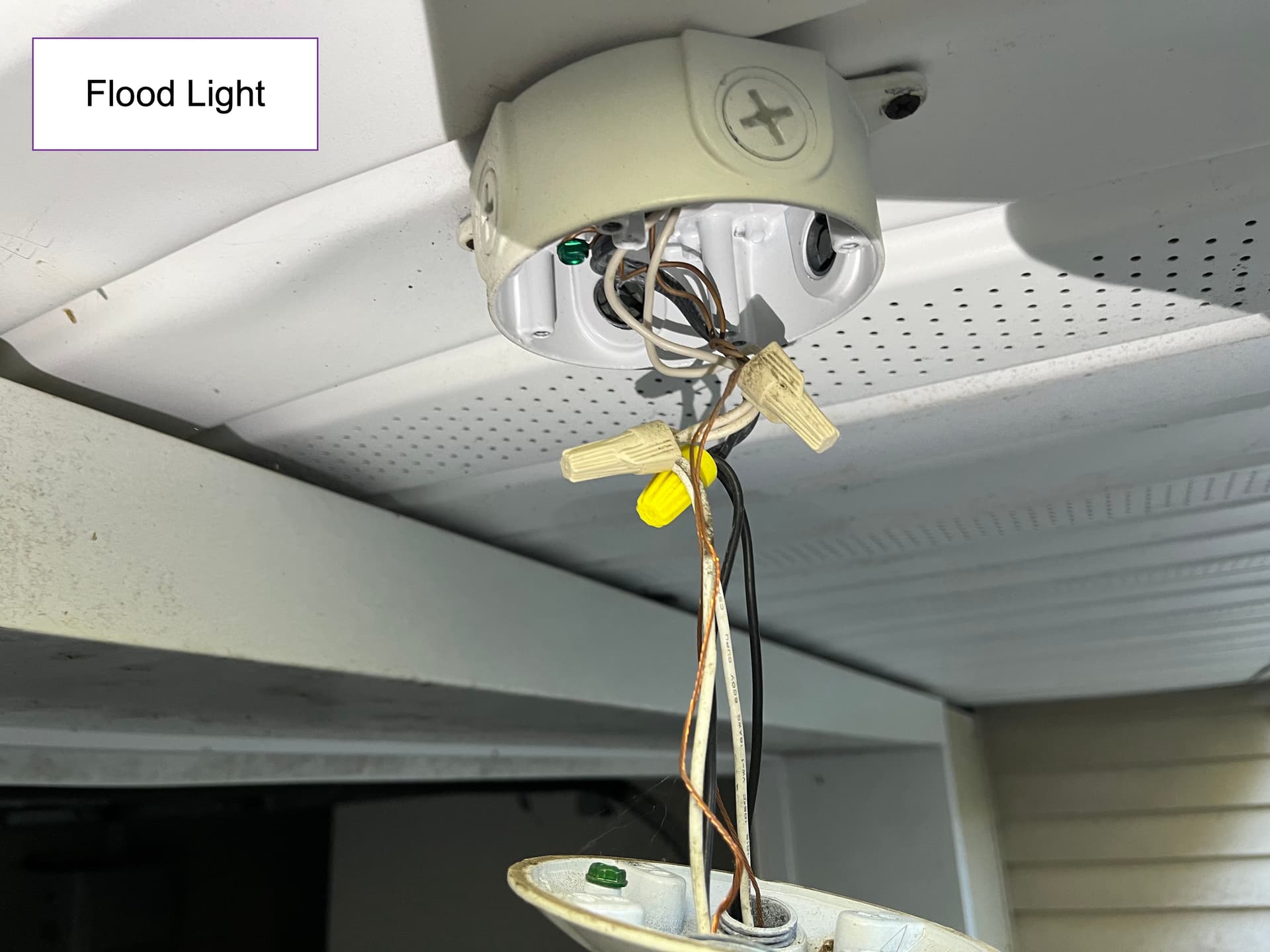
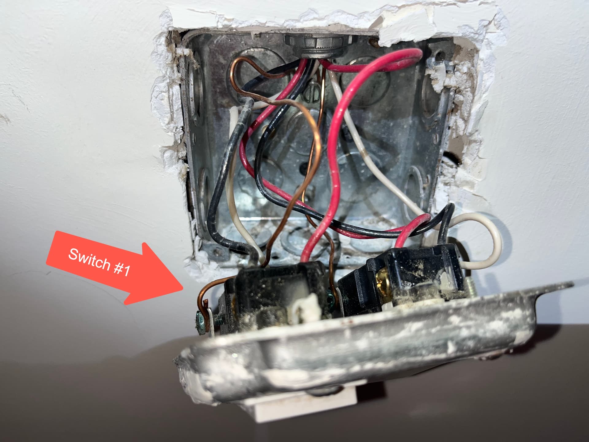
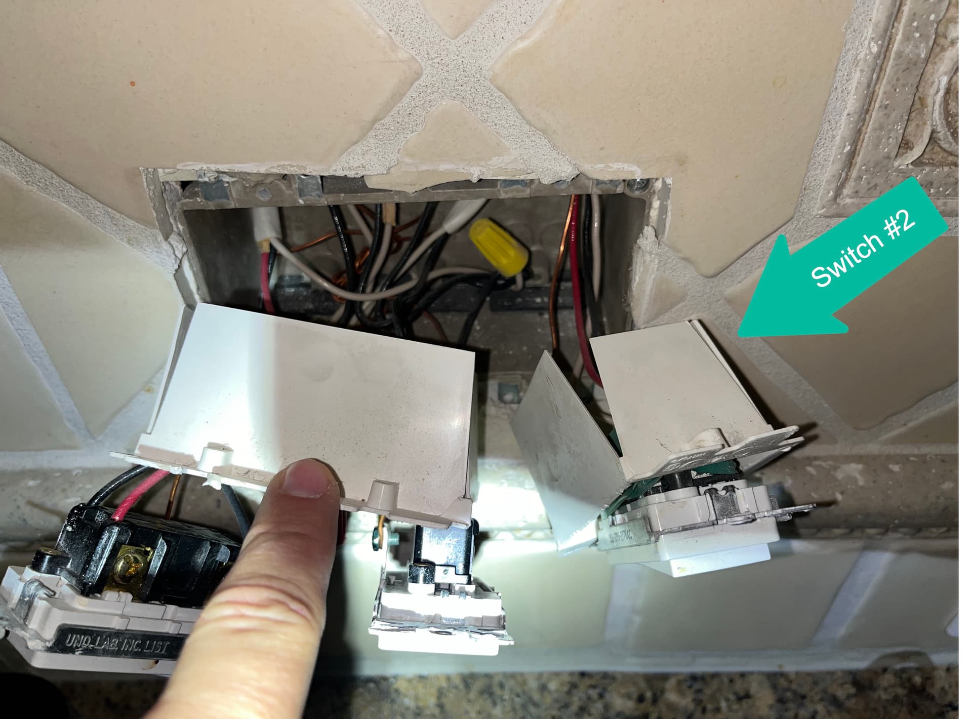
It is an outside floodlight controlled by 2 switches. In the flood light electrical box, there two 2 wire cables (black & white). There is not a red traveler in the box. In both switch boxes there is only a single 3 wire cable (Black, White & Red).
I cannot sort out how this is wired currently (it worked fine with the dumb switches) nor how to possibly convert this to a smart switch and an accessory switch or 2 smart switches (I will use a dumb switch as the second switch if necessary).
Is or was there more than one floodlight? Since all the blacks in the floodlight box are tied together (and the same thing for the whites), power is arriving into that box already switched. I am thinking that one of the two 2-wires coming into the box is switched and the other is going to another light (or a light that at least used to be present).
Separately test between the black and white of the 2-wires coming into the box. My guess is one pair will be either hot or not as you flip your switches. The other pair will be dead regardless of switch position. I see you did some testing but not sure if you flipped switches in the process.
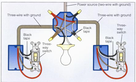
Regarding how this is switched is still a bit of a mystery. You stated that at each of the switches you only have one 3-wire. If this is the case, that indicates power to the light with 3-wires run to each switch. I’ll post the diagram below. The problem is that those 3-wires aren’t in the floodlight box, which makes me think there is a junction box somewhere with those connections, with a 2-wire going to the lights.
So look around for a junction box and/or another light.
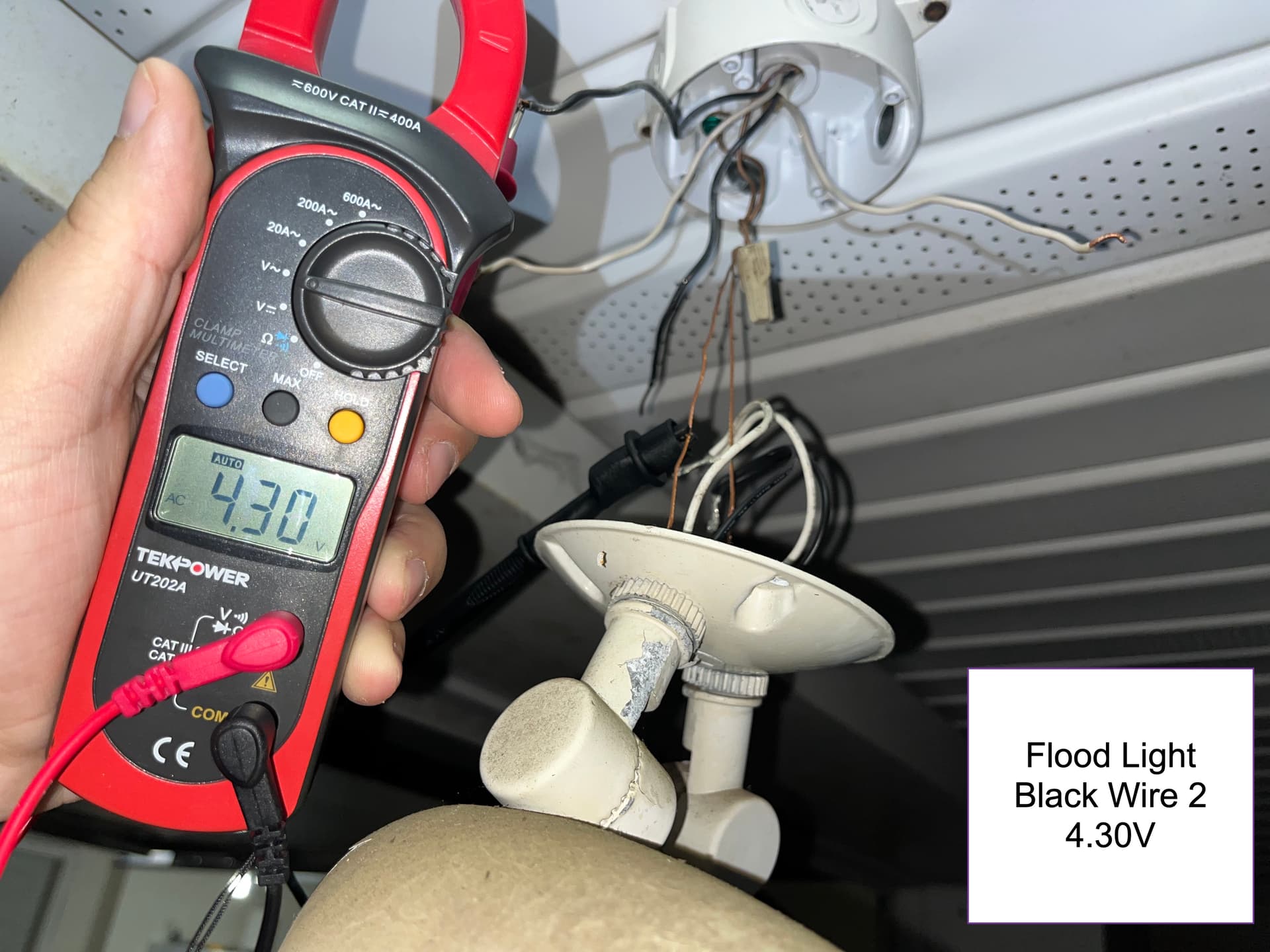
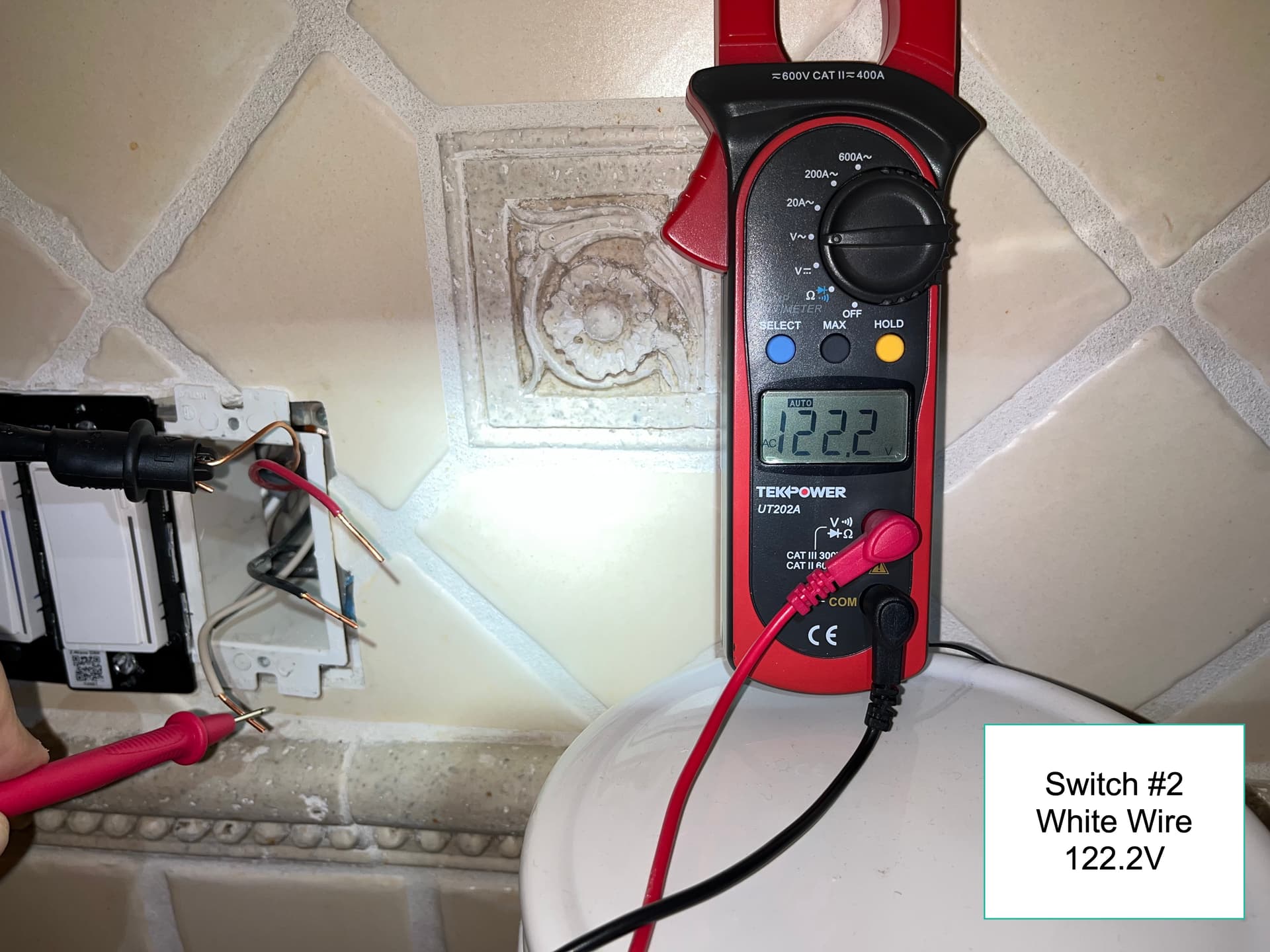
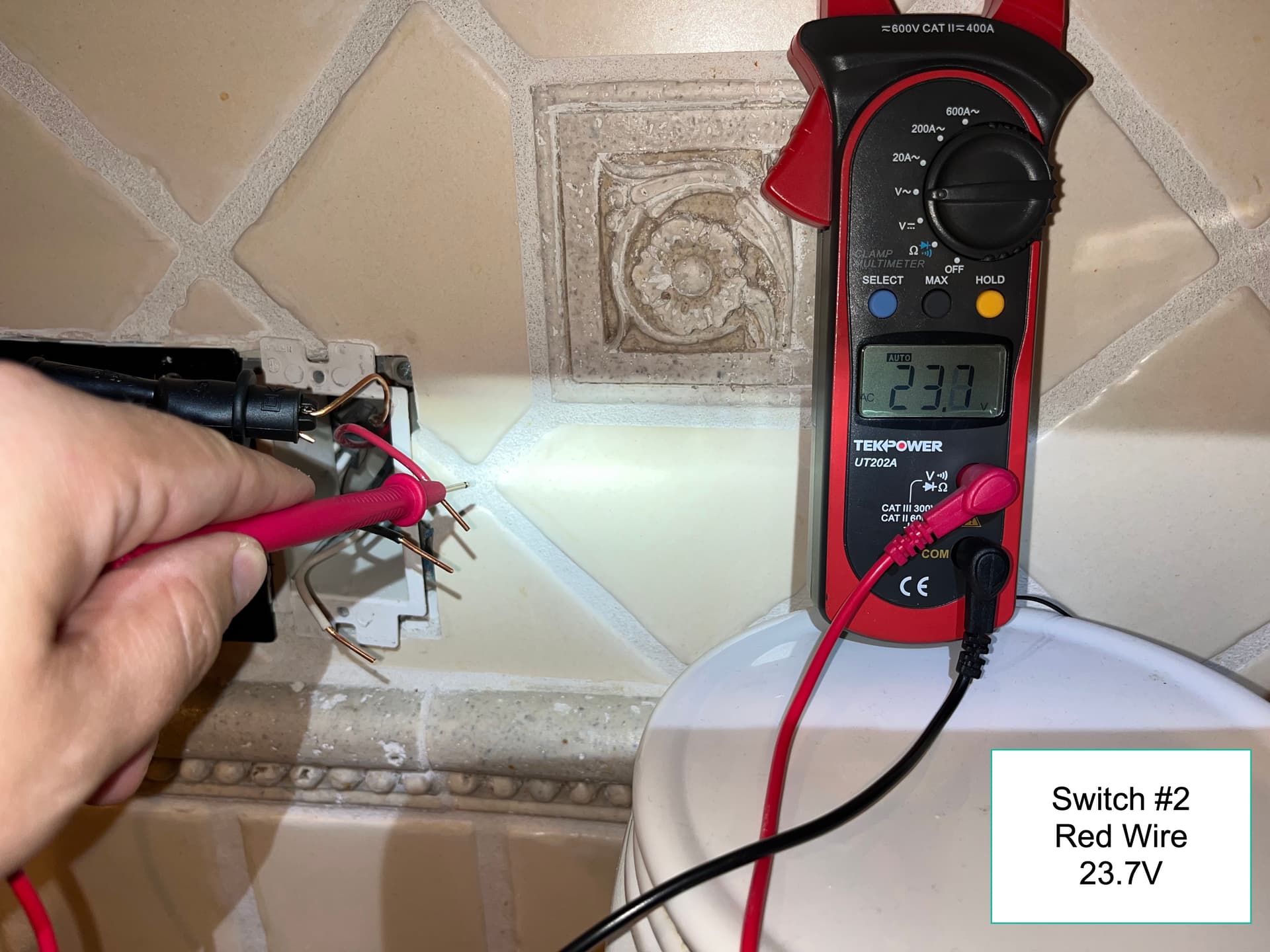
Just so you are aware, the only testing you need to do here will be to determine if a conductor is not or not. That means 120VAC or nothing. The measurements you made where the voltage is somewhere in between is just ghost voltage and of no meaning with what you are trying to figure out here.
I only bought this house a couple of months ago so I’m not sure what used to be there. I don’t see any obvious place where another flood light may have been, but I’ll look again tomorrow for sure.
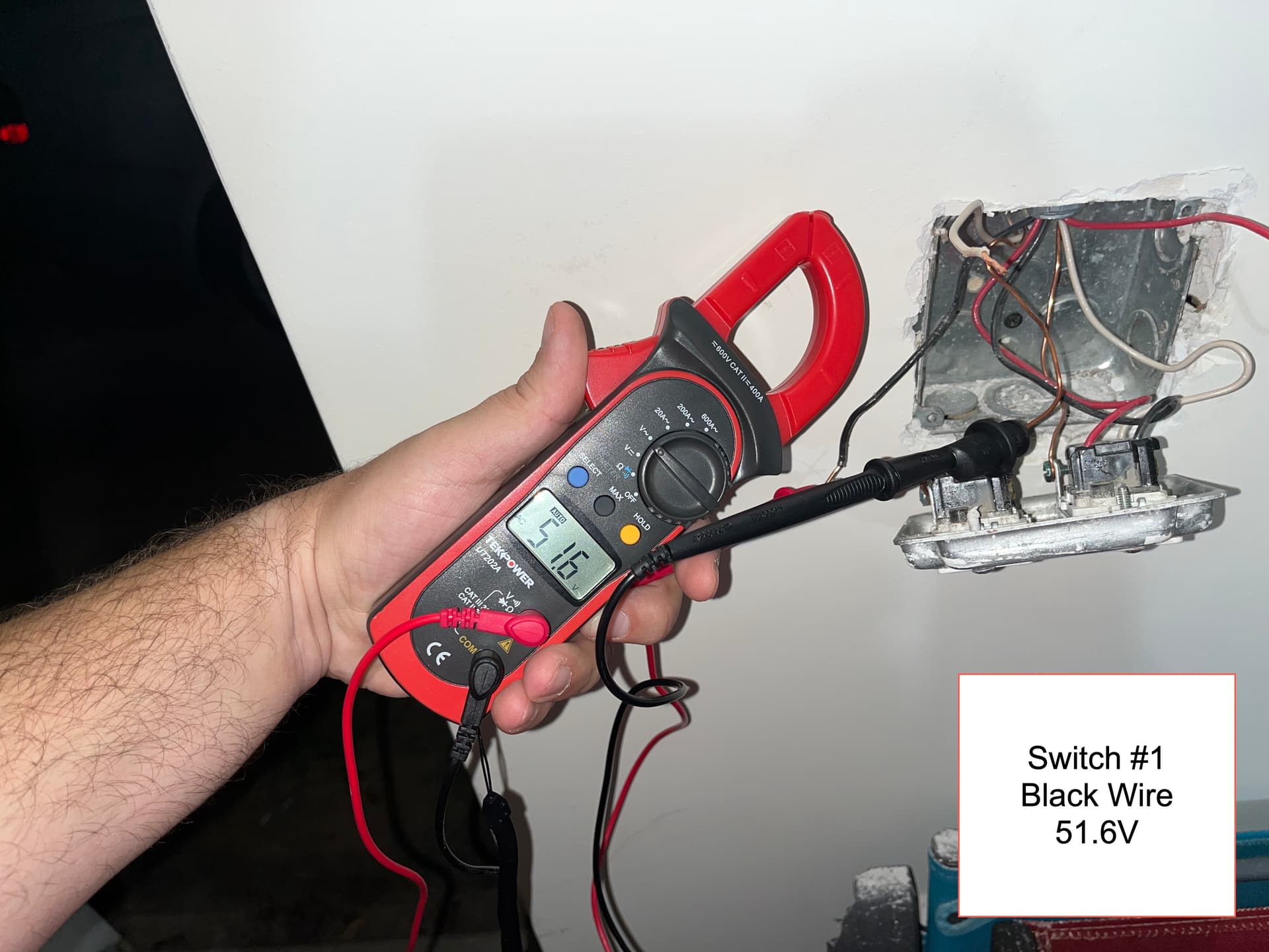
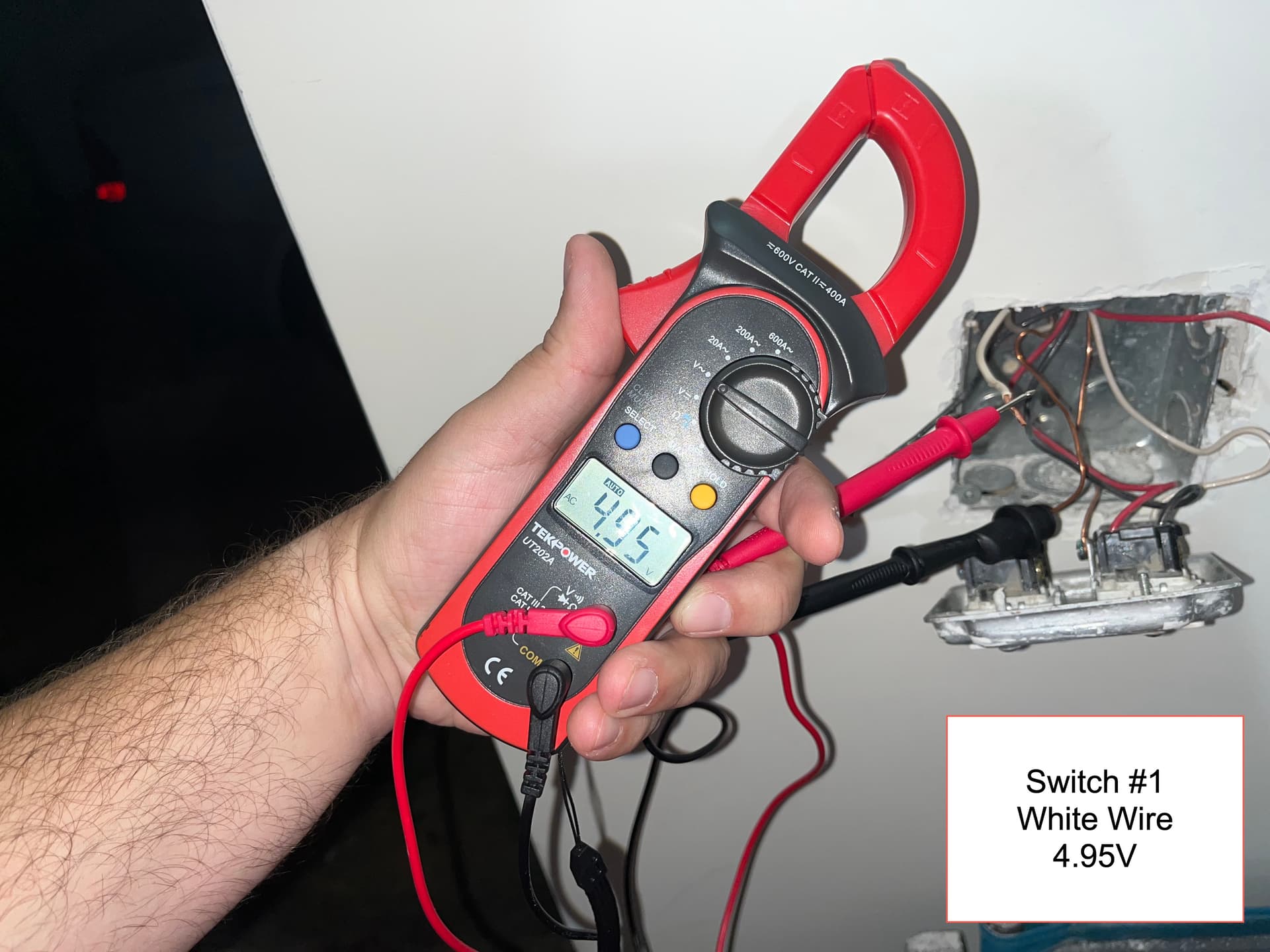
Understood that those lower voltages are ghost for sure, but 50V seemed high to me for ghost voltage.
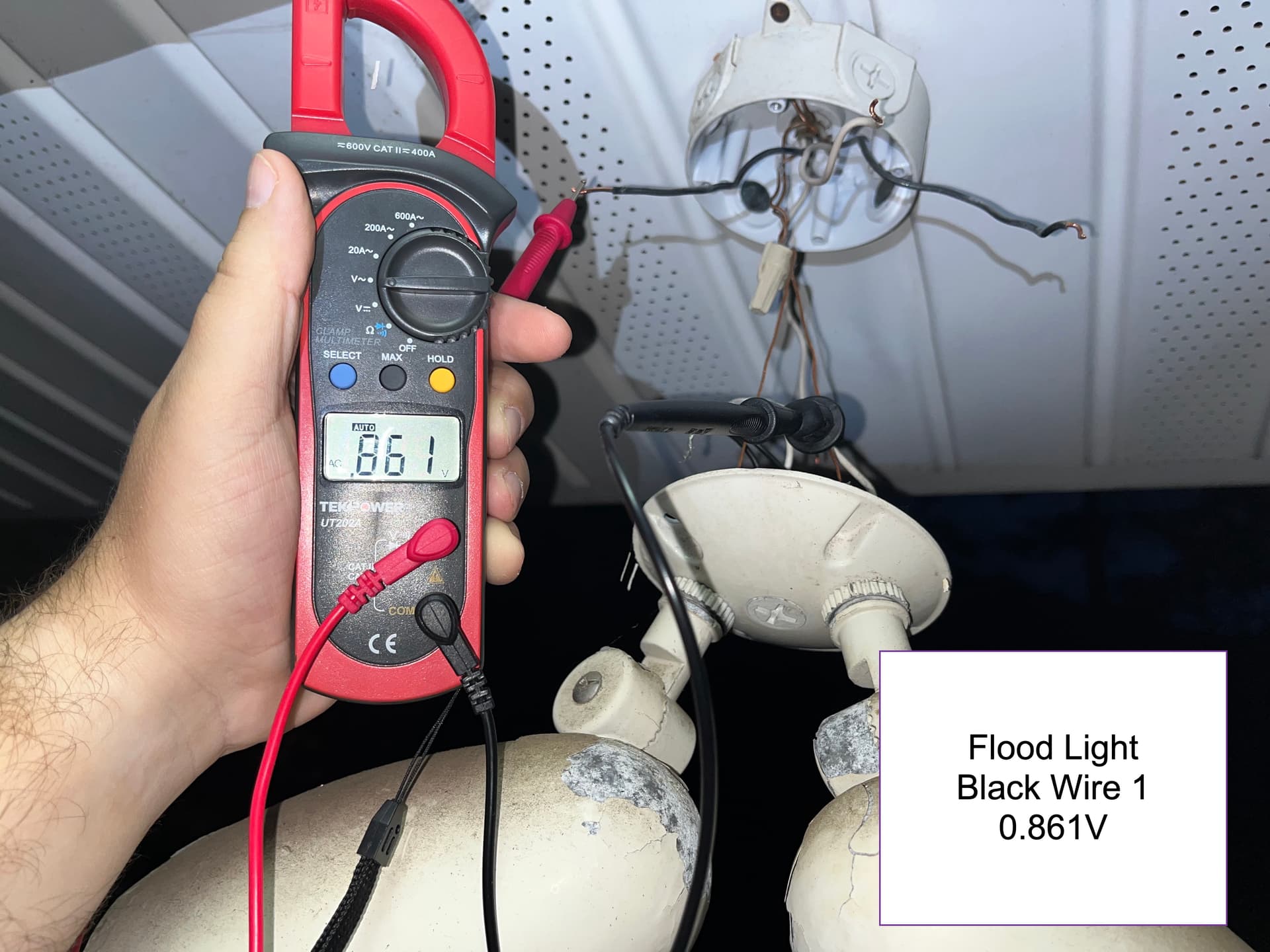
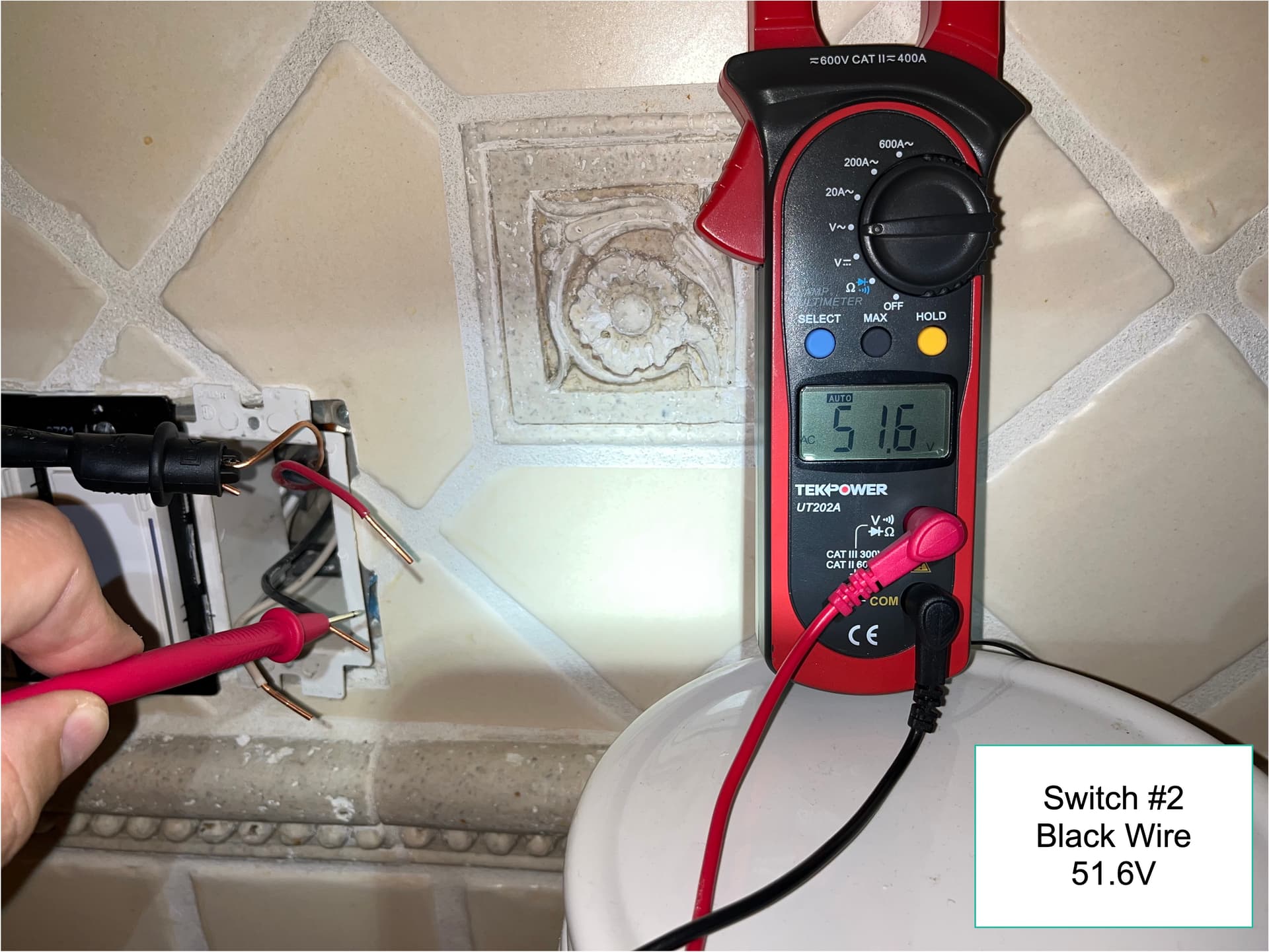
My other issue as that the only wire that has 120V is the white wire at Switch #2. I did not find 120V at the Flood Light from any of the 4 wires.
All of my multimeter testing was with all of the wires unhooked and circuit on so I did not flip any switches to test. But, I’m happy to wire the dmub switches and the flood light back up to test anything you’d like me to check.
When you tested, did you flip the switches? There has to be 120VAC at the floodlight at some point or the lights wouldn’t work. So if you test at the light and there is no voltage on either pair, flip one of the switches and you should see 120VAC on one pair.
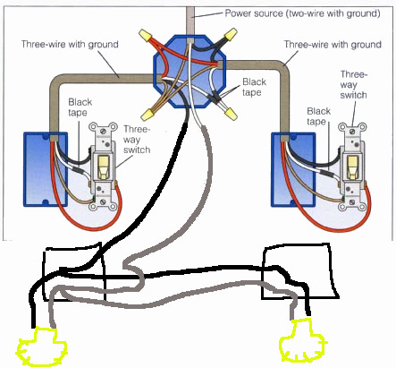
This is what I was thinking as I described in my first response:
Switch box #1 seems to have a conduit connector coming in the top with 2 red, white and blacks. If that actually is a conduit then it has to go somewhere with those same wires coming out at the other end.
Maybe there is another switch box that doesn’t have any devices that control this light but is being used as a junction box for this wiring.
I’ll rewire the dumb switches this afternoon and re-test. I agree that 120V must be getting to the Flood Light in order for it to work. However, it appears that the Line may actually be the White wire at Switch #2 as that is the only one with 120V when all of the switches and light are fully disconnected.
As for in Switch #1, I’m pretty sure those are two 3 wire Romex cables coming into the box and not a single 6 wire conduit, but I’ll look again shortly.
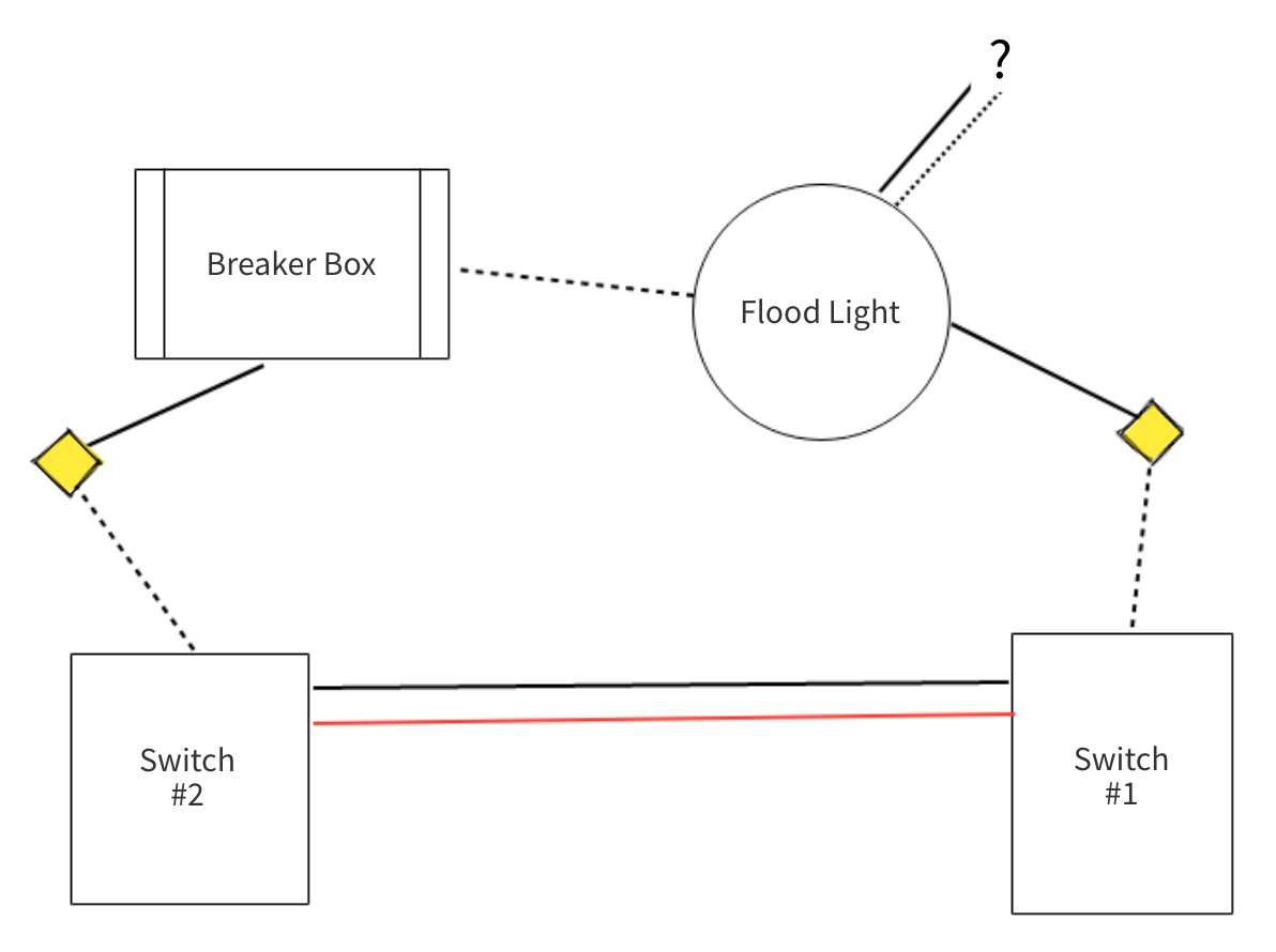
Ok, I mapped it out and this is how it is currently wired. Some “magic” somewhere in the wall happens where the yellow diamonds are. I agree that the 2nd black and white wire in the flood electrical box may have powered another light in the past. I just capped it off for now and have’t seen any lights out or anything like that.
So … how can I wire this with a smart switch? I presume I’ll need to use a Dimmer, non-neutral. I’d like to use an Accessory Switch or 2nd Smart switch instead of a Dumb switch, but I’ll take what I can get.
I’m not convinced that the 3-wire goes directly between the two switch boxes based on the limited view with your pictures. If that were the case, then there would have to be other conductors attached to those switches. You likely wouldn’t see one of each color attached to each switch.
What makes this difficult is that you don’t have Romex, you have conduit and THHN, so diagnosing from pictures is much more difficult. There are no absolutes when it comes to colors, but I’m still leaning toward something along the lines of the drawing I posted. Somewhere there is a junction box, or even maybe a switch box being used as a j-box that has some connections you need to look at.