Hey guys,
Is it possible to use a LZW-31SN on a 4 way setup that doesn’t have a neutral at the box where the constant line is? Seems as the black hot might becoming from an outlet below, and the red and white wires are being used as travelers.
Seems like the light fixture has a neutral that is probably tied to a neutral bundle somewhere.
My other switch boxes with the 4 way switch and the last 3 way with the load have neutral bundles.
The short answer is yes. Basically you wire the Inovelli as it would be a 2-way non-neutral, but then send a hot and a traveler to the Auxs over the 3-wires connecting them.
I’d encourage you to test and diagram out your configuration. If you have a non-neutral light switch configuration, then the hot comes from the light. Your comment " Seems as the black hot might becoming from an outlet below, and the red and white wires are being used as travelers" does not make sense to me. I suspect that your wiring configuration is not what you think, or you have some really non-conventional wiring situation.
The box with the constant hot only has one romex entering the box from what looks like the bottom. Black, White, Red, Ground.
Found the constant hot by disconnecting all the switches and looking for which box has the hot wire… never thought to check the actual light fixture for a hot.
Also, can I use dumb 3 ways with no neutral like this or do I need add on switches?
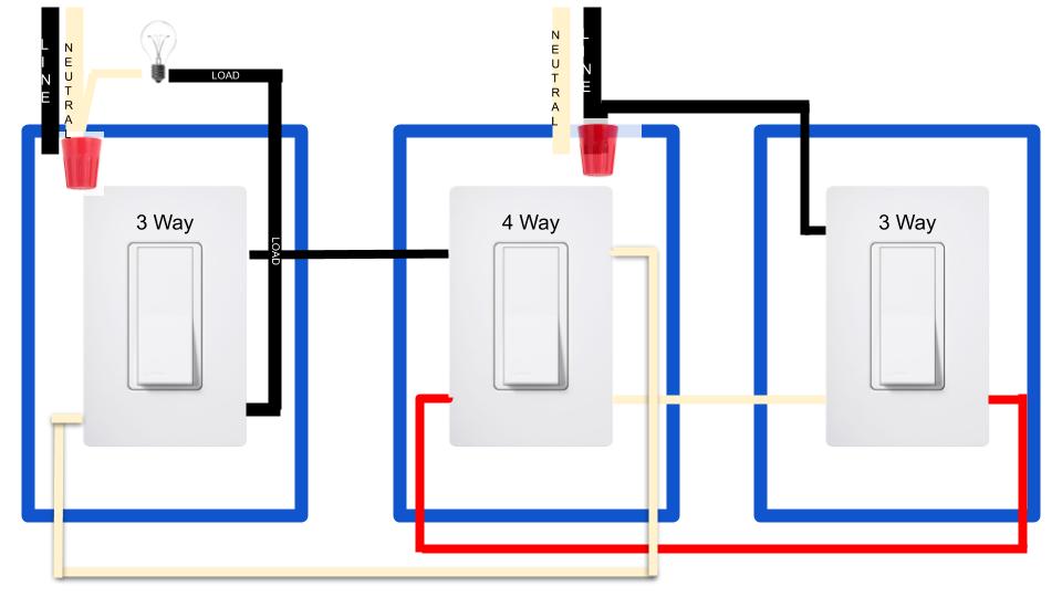
So this is what my wire and switch configuration looks like.
Box with 3 Way Switch (Load)
Romex with Black & White traveler from 4 Way connected to switch
2nd Romex with Black going to light from switch Note : This box has a HOT bundle and a neutral) bundle
Box with 4 Way Switch
Hot bundle comes in here.
Romex with Black (Spliced to HOT bundle), Red, White, Ground – Goes to 3 way box (no load)
2nd Romex with Black and White Traveler – goes to 3 way box (load)
Box with 3 Way Switch (No load)
Black (Spliced to HOT bundle), Red, White, Ground connected to switch-- all coming from Box with 4 way
Hopefully this makes sense, definitely not what I thought it was.
Can you draw it out? It’s difficult to understand from just an explanation. Plus, a drawing takes the characterization of wires out of the equation. I find that when labels just as “traveler” are used, it just serves to confuse, as they are incorrect as often as they are correct.
So looking at your diagram, you are saying that the box on the right (Box 3) only has a black constant hot? Did it come in on a 2-wire?
And the box on the left (Box 1) has a black feeding the light? What is the white conductor doing?
There is a constant hot at the light, but only the neutral is connected? What is the accompanying hot connected to?
And there are only 2-wires between the three switches? Conventional 4-way circuits use 3-wire Romex between the switches?
While nothing would surprise me, this is totally unconventional. I’m not yet convinced that’s what you have. Post back with answers to the above. I’m thinking pictures are next . . .
So there is a 3 wire (14/3) at the 4 way Box
Black - connected to”Hot” bundle
Red and White connected to back 4 way Switch
Ground - connected to ground bundle
The 14/3 goes out the box and in to the 3 way box to the right that is located on a different wall (This is why I thought the constant hot was at this box, not realizing it was coming from the 4 way box)
Back at the 4 way box, there is a 14/2 with the ground connected to the ground bundle in the box.
Black and White wires are connected to the remaining 2 terminals on the back of the 4 way switch, goes out the box to the 3 way box to the left on a different wall.
In the 3 way box to the left the 14/2 Black and White wires run to the switch and ground to the ground bundle in the box. Another 14/2 connects to the common on the 3 way and up out the box, white wire connected to the neutral and ground connected to their respective bundles in the box.
With the power on, the light fixture has no hot wires.
The 3 way switch to the left has no hot wires. (Just the hot bundle in the box, which has no wires going to the switch)
No worries. Don’t want to see them. They just confuse a diagram.
There should actually be 2 14-3 at the 4-way box. That’s just how it works. We’re going to have to do this with pictures . . . one box at a time or it gets confusing. Lets label them Box 1 for the left, Box 2 for the 4-way and Box 3 for the right.
Please post pics of Box 3 (on the right in your diagram) with the switch pulled out. So that I can CLEARLY see both the connections to the switch and INTO THE BOX.
We’ll diagram based on your pics.
Not everything is making sense yet, so we do this in a systematic way to diagnose.
So I had an electrician friend come by and I was right. Looks like I will have to go the add on switch way, he confirmed that only a 14/2 runs to the from the 4 way box to the 3 way switch to the left that has the load on it. Basically, they should have ran a 14/3 but electricians will run a 14/2 to save wire sometimes…idk
Glad you had someone look at it. FWIW, that makes absolutely no sense . . or the switches don’t work correctly.
When you wire a 3 or 4 way with a Line and Load in one box you have to pass the hot to the far box so that it can be switched on the way back to the origin. So that takes one conductor, typically the black. The other two conductors, white and red are the travelers both of which are required to make the switching work. So if you don’t have a 3-wire between the 4-way switch and the 3-ways, you’re missing a conductor.
I’d love to hear your electrician’s explanation of how that could work. If he explains it, post back. Would love to know how you do that!
So he said to think of it as wiring a 4 way setup with 14/2. Basically “14/2” going to each 3 way, they used the 14/3 black wire to just pull power from the 4 way box to the 3 way on the right.
Here is where I also realize that my diagram is wrong for the 3 way to the left. The load wire to the light is coming from the “Common” on the 3 way, not as I have it pictured… Sorry for any confusion…
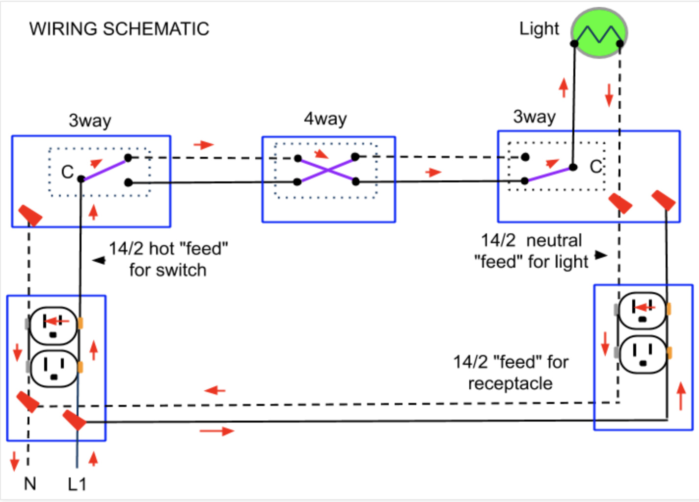
Essentially this is what i have, just flipped, minus the outlets and line comes from the 4 way.
That makes sense, thanks. That drawing is using the neutral from the receptacle leg and is the functional equivalent of two 2-wires between the switches. That drawing has the receptacle Romex passing the neutral to the light. This works since the Line and Load are in different boxes.
I still don’t completely grasp your power feed, but as long as you understand it, that’s what’s important. Let us know how you make out!