Issue i face is the dumb switch needs to be in down position position in order for the smart switch to turn the lights on/off. If the dumb switch is in the top position then the smart switch does not work/looks to not being powered (I changed config to have LED light on even in the off position).
As this is the LZW30-SN model, i do not believe any parameters needs to be changed unlike the dimmer version?
Not sure if my wiring is incorrect or I’m overlooking something in the setup…
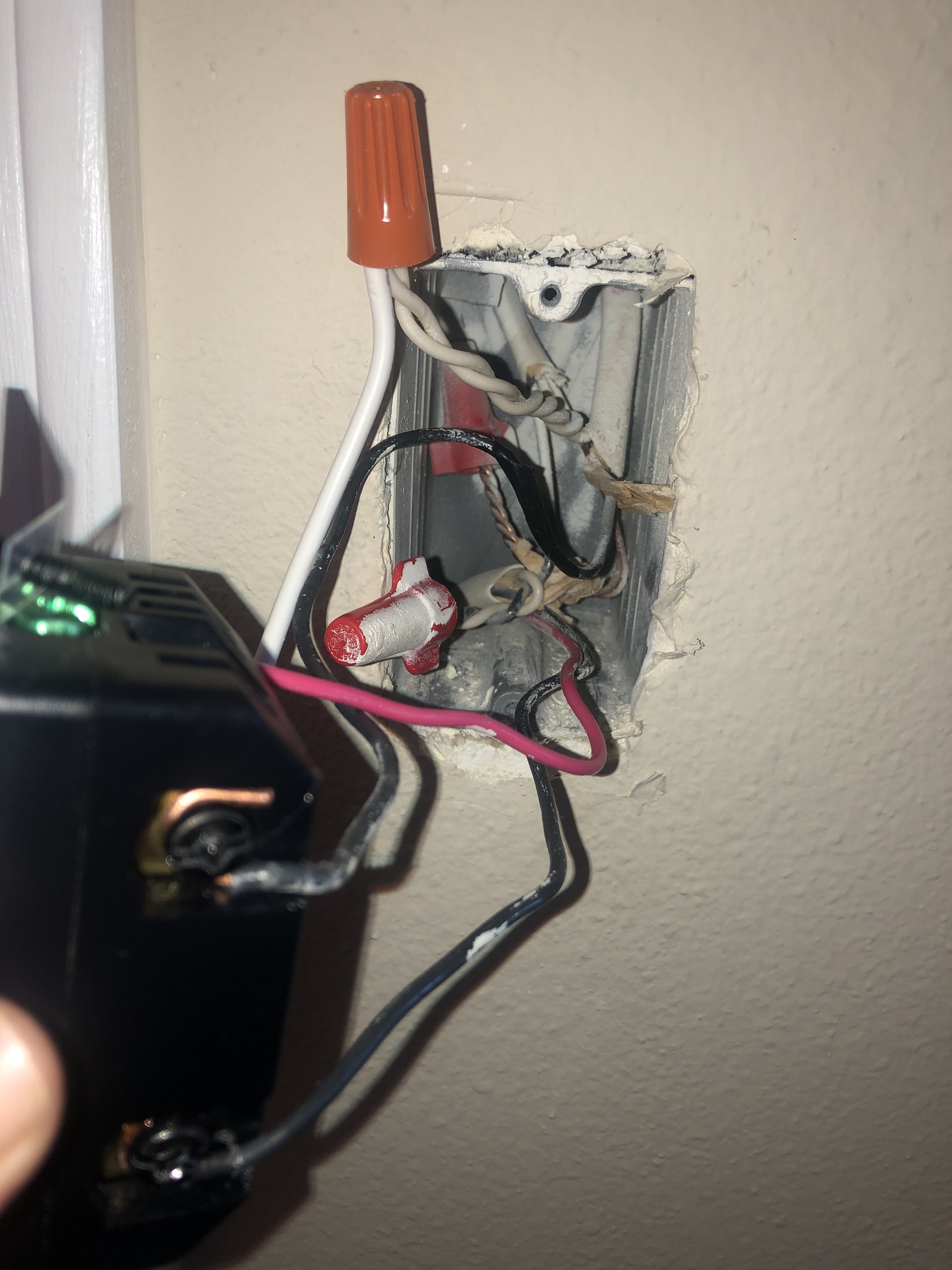
I can’t comment 100% on your wiring as it’s a little tough to see all the connections in the primary box with the Inovelli. A couple of questions:
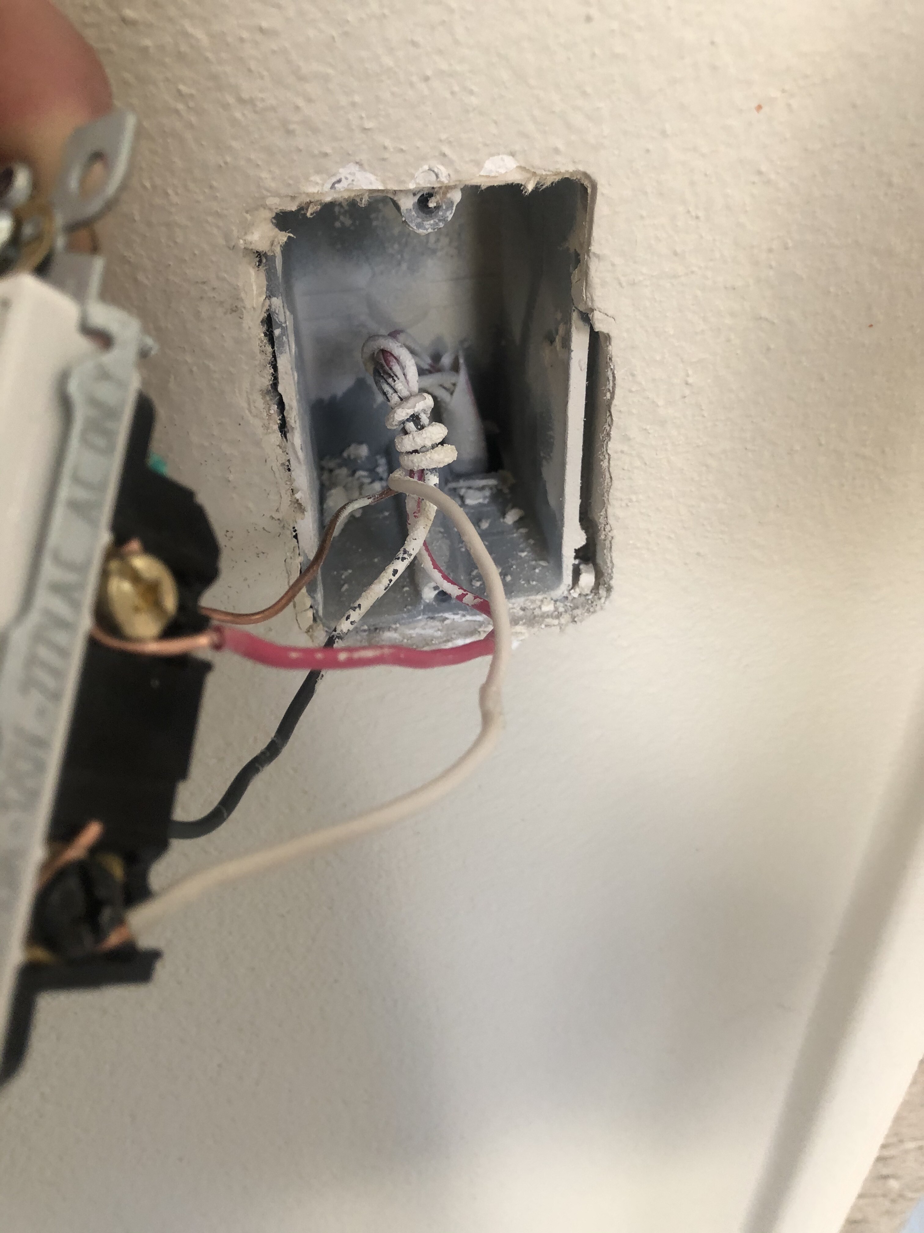
Did you rewire the dumb switch or was it wired like that before? I’m asking because it does not look like it was wired by an electrician and the conductors aren’t on the terminals that I would expect. That does not make it incorrect or unsafe, it’s just a little confusing when you can’t see all the conductors in the other box.
It looks like you have three Romex in the primary box. Two of the Romex are 2-wire. One of them is going to be the line and the other is going to be the load. How did you determine which was which?
What is your load? If it is an LED, try swapping it out temporarily with an incandescent bulb to see if that makes a difference.
You are correct regarding the settings. The switch should auto detect so there is no switch type to set like there is with the dimmer.
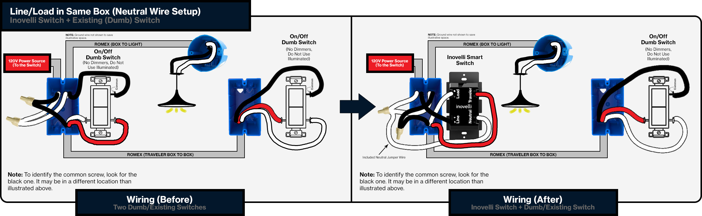
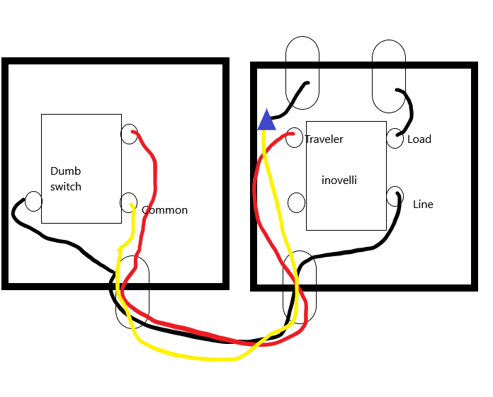
Edit: In the Inovelli box, where are each of the conductors of the 3-wire connected? In your case, the red and the black conductors are the travelers. They should be connected to the load and traveler terminals on the switch. It’s a little tough to tell from the picture but it does not look like those connections are correct. It looks as if the load terminal on the inavelli is connected to as 2- wire wrapped with electrical tape. I could be wrong though.
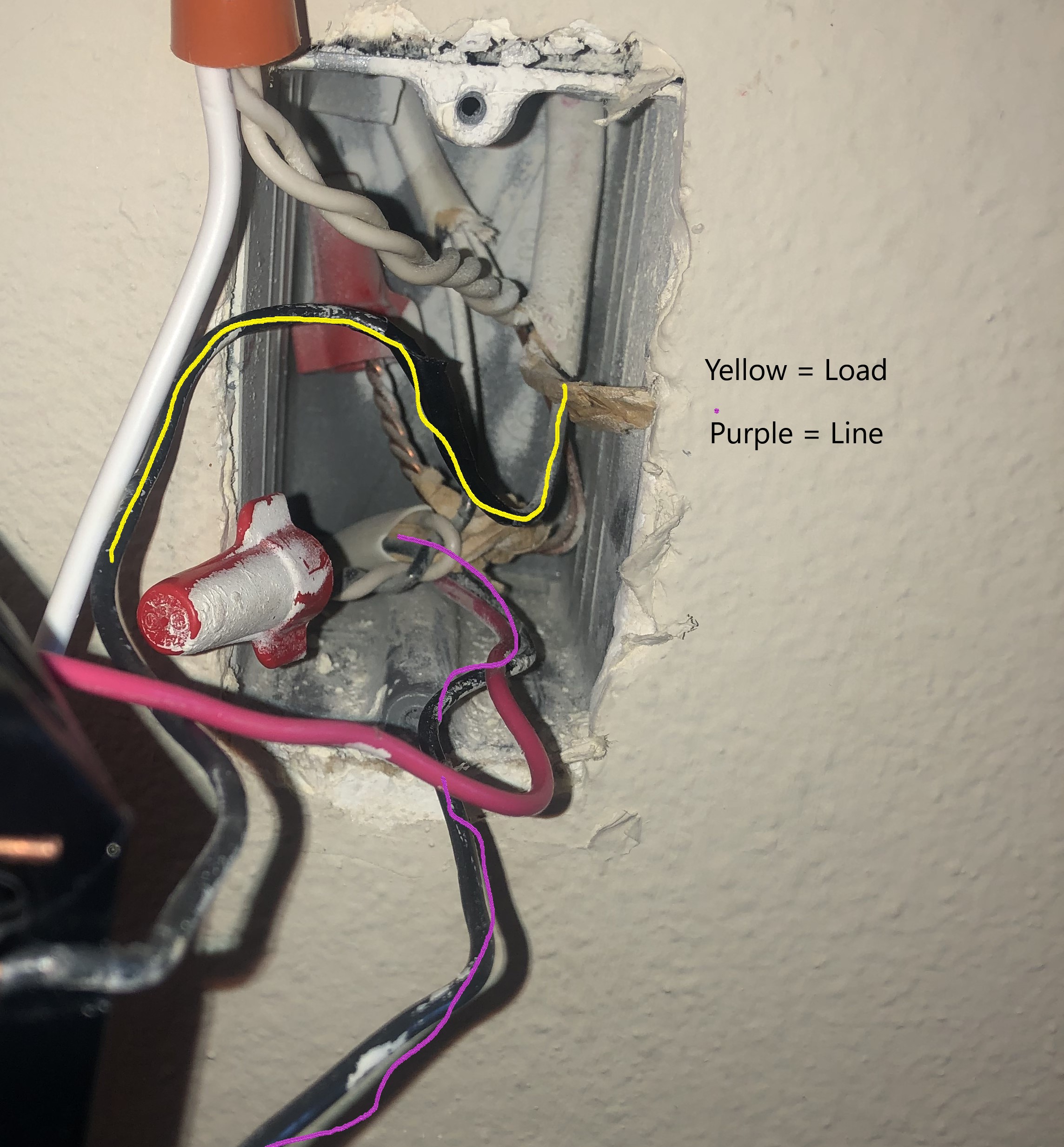
Edit: I drew out the current wiring. Yellow Wire is the white wire. Blue triangle represents wire nut where the white/black are tied together. I did not draw out the neutral or ground to keep the diagram simple.
Okay, I think you have confirmed what I thought before. Look at your picture where you highlighted the load wire and you see that the load wire is connected to the switch, right? Now look at the diagram that you posted and you will see that the load wire is supposed to be connected to the white of the 3-wire. (I know the diagram shows the black wire but that’s just because you’re dumb switch isn’t wired the same.)
See my post above. The black and the red conductor from the three wire are supposed to be connected to the load and the traveler terminals.
I think i got it. I Need to make the following adjustments.
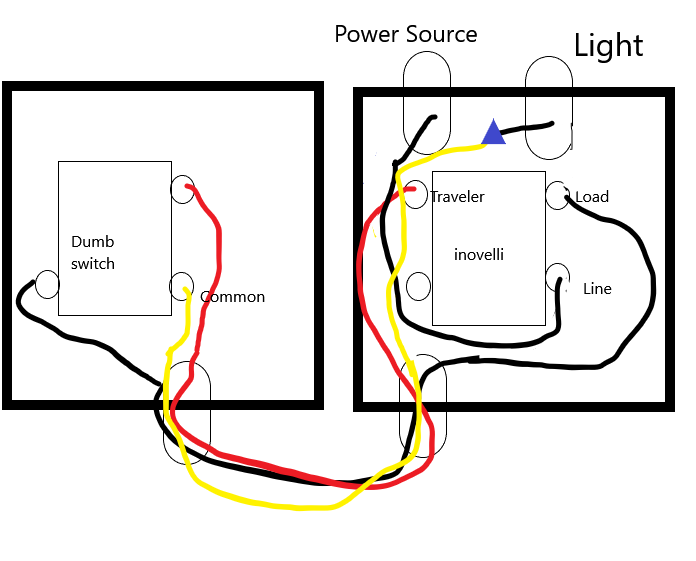
1)The line wire should be connected directly to invoelli switch. Currently it’s connected to the Common wire via wire nut
2)The now, unbundled Common wire (white in my case/Black In Inovelli diagram) should be connected (via wire nut) to the load wire (wire connected to the light)
3)Black Wire (white in Inovelli diagram) currently connected to “Line” should be moved to Load.
That sounds correct. Do not forget to pigtail a neutral from the neutral on the 2-wire line Romex to the neutral on the switch.
I see what you did originally now. You retained the old dumb switch wiring scheme where the hot is passed to the other switch first. As you can see now, adjustments have to be made with a smart switch.
Just got around to rewiring based on above and it works. Appreciate the walkthrough. You’re exactly right, I kept the old dumb switch wiring. I think when I initially review the diagram I misunderstood the routing and never properly sat down to review again.