I’ve figured out most of the wiring here on my new home. The electrician certainly did some corner cutting and a few of the switches I wanted to automate don’t have neutral wires, which is making my life rather frusturating. None of the colors of the wires are reliabile at all, so I’ve had to mainly figure this out as I go.
I have run into another situation I am hoping to get some help on. In my master bedroom, the main lights for the room are on a 3 way switch. One as you enter and one near the bed so you can switch it from bed. This is the one I want to automate.
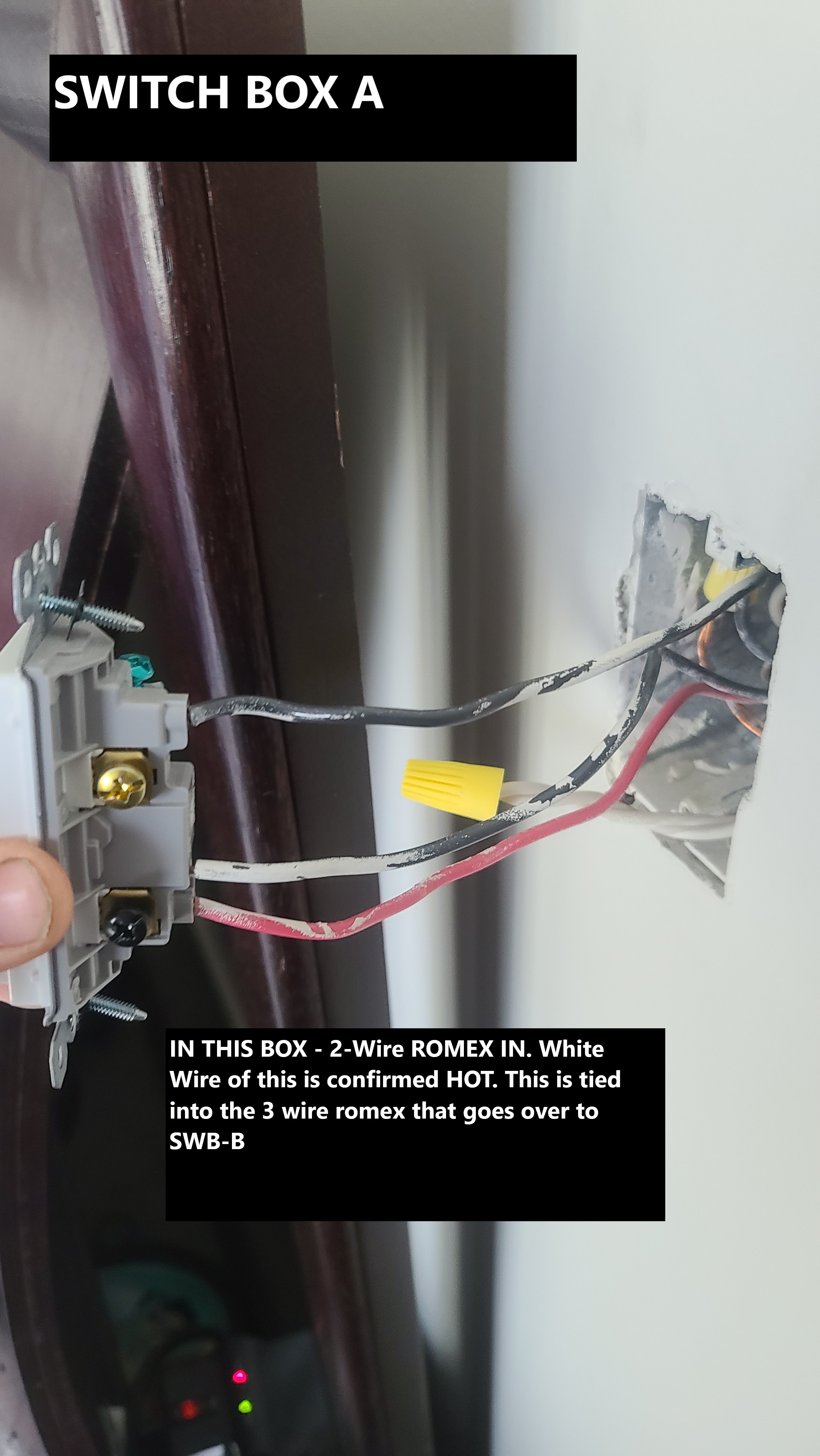
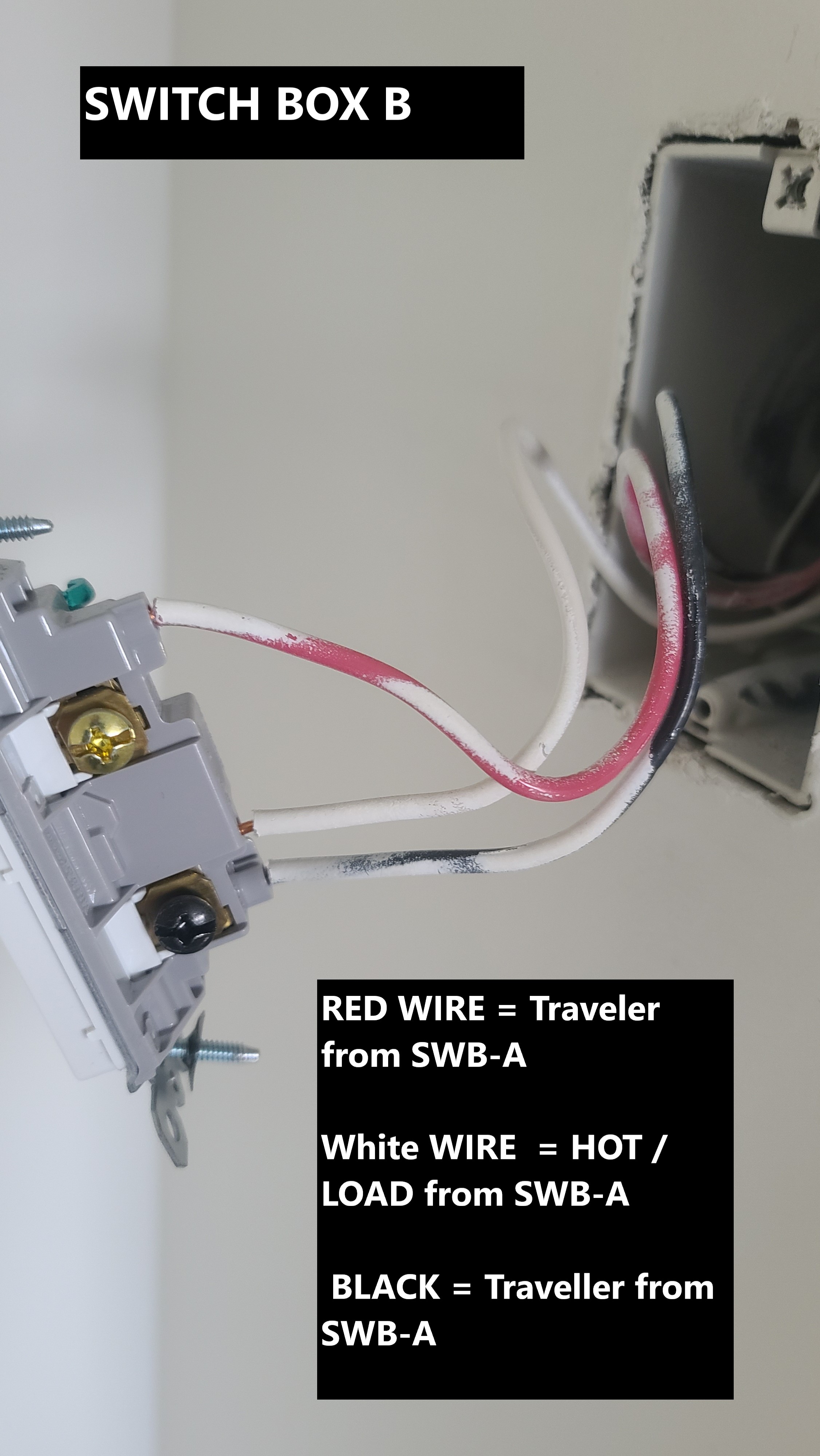
I’ve uploaded photos showing what I have. SWB-B has just one 3 wire coming to it from SWB-A
SWB-A has a 2-wire coming into it from I think the lights? or perhaps that is from the panel. I can’t tell exactly. Either way it’s looking like I don’t have a netural wire in there. Is there a way I could make a non-neutral switch work here? or am I better to try to run a new neutral wire from where?
Crappy part is a year after my house was built (built late 2019) the new code requires a netural in every single box (argg).
I’ve uploaded pics here. Can anyone think of away to make this work? or am I shit out of luck. In one of situation I have a box in my house with no neutral wire. I attempted to use the non-neutral Invoelli switch but it didn’t work well at all. I don’t think there was enough load as it only ever sort of “flickered” and I had to use a AOTEC bypass which didn’t work all that well.
Just double-checking. Are you SURE the white is hot? Did you use a meter and after separating the two wire-nutted whites in Box A. Test between the white on the 2-wire and the bare ground?
Just double-checking because it’s hard to believe that in 2019 there would still be power to the light wiring. But nothing would surprise me. BTW, the requirement for a neutral at a switch point came in with the 2011 NEC. Of course, your authority may not have adopted that code when your house was built.
Even with the non-neutral, it’s doable, but confirm that you get a constant 120VAC Box A, testing between the disconnected 2-wire white and the bare ground.
Yep 100% sure. I disconnected all the leads on both switch boxes and checked. Nothing on box B and white wire is reading 120v ac in switch box A. I initially thought that was my neutral wires ae that is how its been on a couple of other lights in the house. But as mentioned nothing is consistent and its super annoying.
Im in bc Canada so not sure if code was different from nec?
Ok, thanks for confirming. But I’m still confused about what I’m seeing.
So let’s say your power is coming from the light as you would have in a non-neutral. At the light, the hot would typically be connected to the white on the 2-wire (so that matches). The black on the two-wire is connected to the light. So the power comes into the box via the white and back to the light on the black.
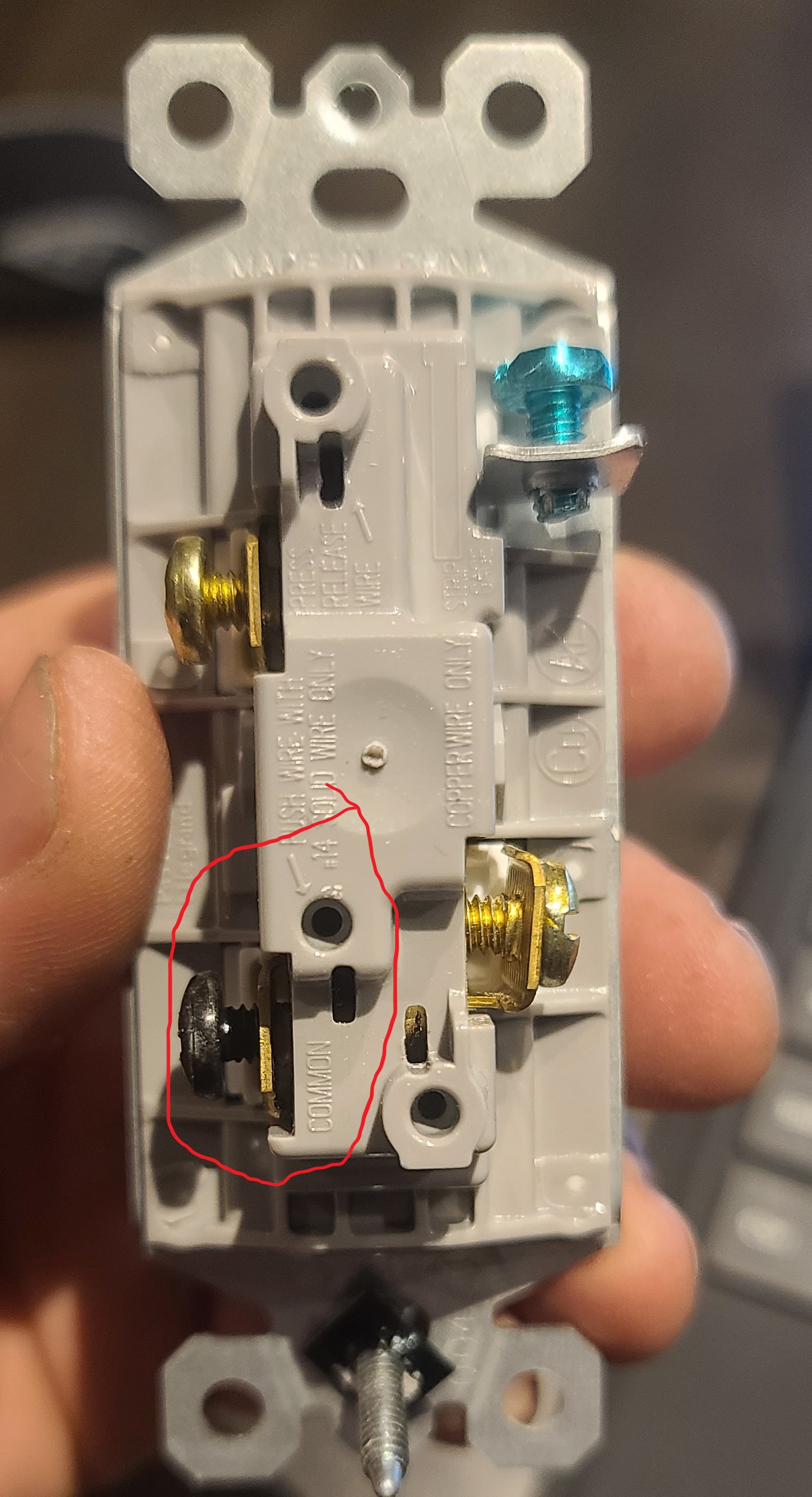
So with a 3-way, the power has to routed through the other switch. So in your case, in Box A the white which you say is hot you believe is sent to Box B via the white on the 3-wire. In Box B, that white (hot) would have to be connected to the common terminal on the switch (black screw) so that the switched power can be routed back to the first box via the travelers. But in your case, it does not look like the white is attached to the common screw. It looks like it’s attached to a brass terminal.
Take a look at switch B as the picture doesn’t have a good perspective. Confirm that the white is not connected to the common terminal.
Is this 3-way working properly? Both switches?
If you draw this out you’ll understand how this can’t work as it’s presently wired, unless I’m mistaken about the terminals the conductors are connected to.
Edit: Can you please explain in detail how you measured in Box A. Did you use a meter and what conductors did you test between?
Yep Both switches work perfectly. I can the switch on and off from both switches currently. To measure it / confirm. I unhooked ALL connections to both switches in both SWBA and SWBB. The I put my negative onto the copper ground, and tested each wire. The white showed as the only one as constant 120AC.
I’ve uploaded a sketch of what I am seeing in the box as well as couple more photos. Is this still making sense. I can go double check this tommorow, but I am 99% sure that this is what I had earlier.
Thanks. I got the drawing but I’m trying to understand the logic of the switch connections. Take a look at your switch in Box B. Which of the conductors is connected to the black common screw?
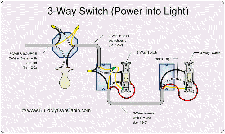
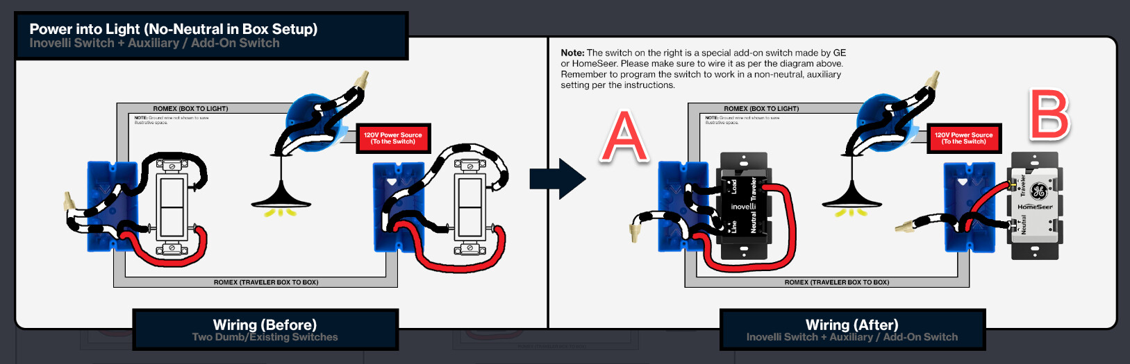
Wiring looks similar to this diagram, except white/black are swapped from the light fixture to switches. Watching for your response to Bry’s last 2 questions.
You may have to consider a nano switch at the light fixture, or smart bulb(s) and repurpose the wiring from the light to your two switches to provide hot/neutral simply for powering the smart switches.
Are you able to look in the box at the light fixture?
Sort of like your drawing except in this case it looks like the hot is being sent to the other side first, whereas in your drawing it the hot starts at the first switch. It’s typically done like your drawing, but the other way will work as well. The only thing troubling me is that I’m not sure the hot in the far box is on the common terminal.
This looks to be a a traditional non-neutral in the first box, so it’s perfectly doable with an Inovelli and no need for a nano. I’m also waiting for a response to my question about the common connection in Switch B.
Thanks your your patience fellas. Wife was asleep in bed last night and got home late tonight. So couldn’t exactly start pulling apart light switches while she is sleeping lol. Anyway I’ve got more confirmed wiring here for you.
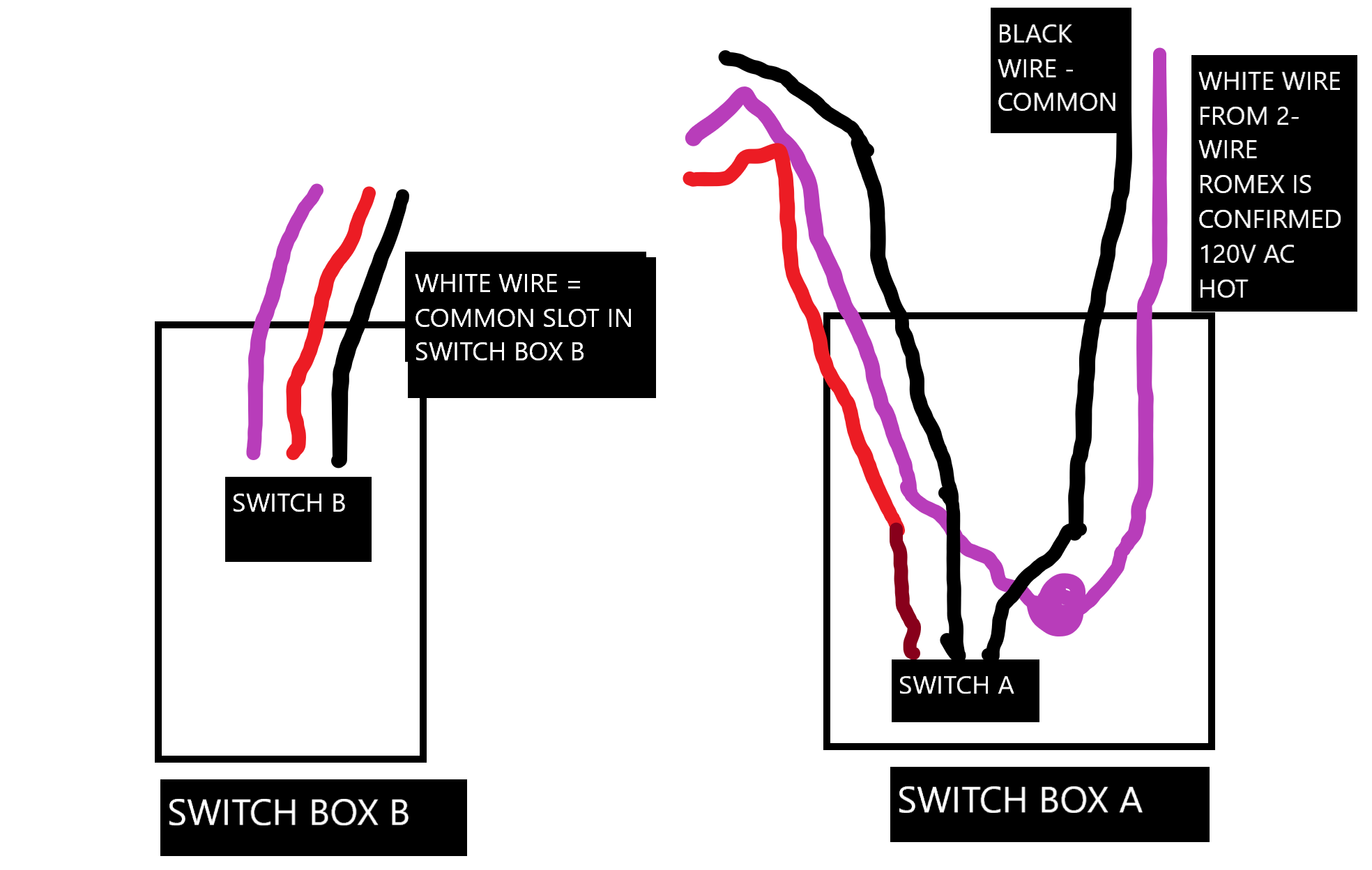
I again pulled both switches apart in BOTH switch boxes and both white wires in SWB A to CONFIRM which wire was the 120V HOT Constant. And it is definitely that white wire from the 2 wire in Switch Box A. I checked what the common wire is as you can which slot it goes into and it’s the black wire from the 2 Wire in SWITCH BOX A. I’ve also uploaded a photo that shows where the common terminal is on these switches (legrand) and it’s the 2nd one from the bottom. When I have all the switches pulled apart there is NO power in SWB B at all. And the only power in SWB A is that white wire in the 2 WIRE (120V AC)
I also updated my drawings here and labeled them. I didn’t show the 3 wire coming from SWITCH box A into SWITCH Box B. While I believe that is how it is connected, I can’t 100% confirm but it’s my suspicion that that 3 wire that leaves SWB A goes to SWB B (and not to the fixture)
Yep. That makes more sense now with you advising that the white wire in Box B is connected to the common terminal. Didn’t look like it from the pictures.
The final test to confirm would be to touch the two conductors from the 2-wire together in Box A. The light should turn on.
So as you suspected you have a power to the light non-neutral. In your case, power starts at the light. It’s routed to Box A on the white of the 2-wire. The hot is then sent to Box B over the white of the 3-wire, where it’s connected to the common terminal. In Box B, the hot is returned switched to Box A. The switched hot goes out of the common terminal in Box A via the black on the 2-wire back to the light.
So you can put the Inovelli dimmer in Box A in a non-neutral configuration. You’ll use two of the conductors on the 3-wire going to Box B to connect to an Aux switch. Depending on your light, you may need to install a bypass at the light. You’ll also configure the settings of your Inovelli as a non-neutral mated with an Aux (3-way momentary)(parameters 21 and 22).
So I guess I will need to purchase another Inovelli Red Series Dimmer. I just used my last one in a bathroom. Does Inovelli make an Aux switch? I didn’t see one on their website. If not which Aux switch would pair well with that?
Hoping I do’t have to wire in a bypass. The lights they are going into are LED recessed ceiling lighting, there are about 6 fixtures total that this circuit is on. I know in my garage I had a couple of LED lights and had to wire in a bypass to those or they just flickered all the time.
Happy to report it’s up and working! Wired it all in as per above diagram from Bry. Initially the main switch worked but Aux switch doesn’t. But for some reason it didn’t save my preferences as Non-Neutral + 3 Way Momentary. After I got that part saved on switch preferences it worked like a charm! Thank you everyone that helped! Love this community.