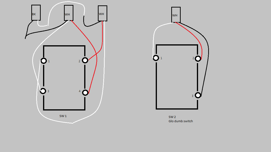
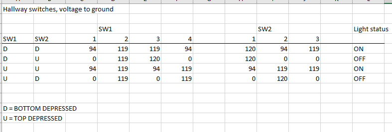
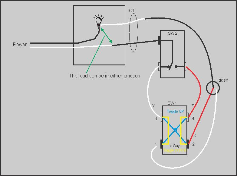
I have what appears to be a 4-way switch and a dumb 3-way that control two ceiling lights. There is a neutral available in the box. It is very difficult to determine what feeds are going where. Below is a diagram of the existing wiring and a table of the voltages on the switch terminals. Drawing is looking at the front of the switches.
HI,
From what you’ve drawn I would expect:
SW2 T3 is colored different from the other 2. Likely black. (pls verify)
The cable on the left is likely power in and the cable to its right is the light. That would make the cable 3rd from the left the other end of the cable on the right.
What does the BK, WH, WH, WH on the cables signify?
Then there is the question of why someone would use a 4-Way switch in this configuration. Is it possible there was another 3-Way somewhere?
Can you look in the ceiling fixture to see if there is a cable (red,black,white)?
Finally, what is your goal?
John
Thanks for the reply. "BK, WH, WH, WH is just the color of the romex jacket. BK is 2 cond, WH is 3 cond. All three S2 screws are brass colored. This was installed approx 1970. There is no “third” switch. The controlled fixture near the 4-way switch has four WH/BK 2 conductor cables coming in. I want to replace the 4-way with the LZW31 to dim and remotely control the two associated hall lights with a motion sensor via Hubitat. Just need to figure out which wires to connect where and then the appropriate settings. I would like the retain the 3-way functionality of the dumb three way switch. If I cant use the dumb switch I can replace that with a pico button remote.
Or, can SW2 be replaced by the LZW31? I do have access to neutral in that box.
I think you have enough wires to do what you want. However the puzzle is to identify each of the wires in the 4-way switch box.
All three S2 screws are brass colored.
One should have a notation like “com” or “common” on the plastic near one of the screws. This part is simply a
This would suggest the far left cable in your sketch goes to the light. How are the 4 wires in the light fixture connected to each other and the light?
The load is dropping th voltage from 120 to 94 across the assorted terminals. I be able to figure out the connections base on the measurements.
Yea I saw the 94’s. At first I thought it was a pickup from an open wire but it seemed too consistent.
If they are real valid voltages then something is very wrong.
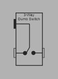
SW2 is a “glow” switch. Internal neon lamp and high value resistor resistor to illuminate the switch. I suspect the voltage is provided by miniscule current read across the lamp. Probably would be zero with a normal 3-way switch. It does incicate where the other end of the wire goes.
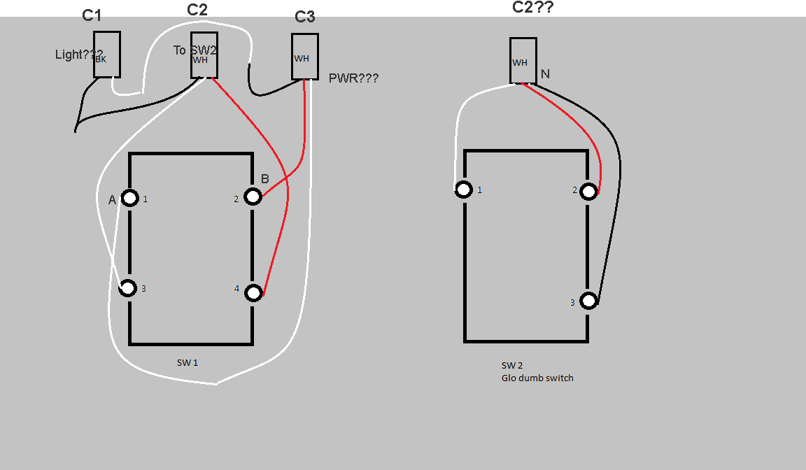
Slight Modification of your dwg:
First question, what are you measuring all you voltages to? You say “ground” is this the green or bare wire?
If it is then…
Looking at the table, It appears, Power is coming in on C3-Red
However all the other wire colors do not seem to follow “std” wiring practices.
If power comes in on C3-Red (as shown in the table) and C1 is the Lamp, then C3-white does nothing. Please disconnect it from the SW1, measure it and verify all lights still work as described.
Note: I think you will be able to do what you want, however the non std wire colors and the presence of a not needed 4-Way (could be a 3-way) drives me to be extra careful in any recommendations.
You might also disconnet all of C3 and measure each to gnd.
I’ll mess with it later tomorrow. I currently believe C3 is connected to C2?? I’ll let you know after I disconnect it. I genuinely have no clue where C2 connects to.
I’t always tough, especially when the colors don’t follow the normal wiring practices.
If you look at your table:
SW1-2 must be power as it is always ON.
SW2-3 must be the light it is the only one that follows the light ON/OFF.
The good thing is I’m sure you can use your dimmer as soon as we are sure of the connections.
John
I had a chance to get back to this. I disconnected the wires from SW1 and the black from SW2. Killed the power and dug out my toner and probe. C3 goes to a third switch and or cable terminations buried in a nearby wall at switch height. C3 RD and BK are always connected and go back to C1 white which is always hot. C1 BK is neutral. Seems like the load is wired into the buried c3 termination. The splices are soldered. C1 - C2 BK to BK. C1 - C3 WH to BK.

The hot/white from C-1 is effectively connected directly to #2 on SW1. Disconnecting the C-3 white wire from SW1 has no effect in any switch position, any readings are from SW1 terminal 4.
Great!
I’ve redrawn your diagram so I could be sure I understood the circuit paths.
This should be the same as you drew (at least for a current path).
Note: with the white wire from SW1-1 removed SW1 is acting exactly like a 3-Way switch.
Unfortunately this configuration is not one Inovelli has verified to work. You can however give it a try. What I’m about to suggest will not damage the dimmer however I’m not sure the Inovelli can “steal” power from a wire connected to the “traveler” terminal.
To replace SW1 with an Inovelli Black or Red:
Wire X --> Inovelli “Line” terminal
Wire Y --> Inovelli “Traveler” terminal
Wire Z --> Inovelli “Load” terminal
Where it might not work is when SW2 is in the position shown. And the circuit goes in the “Traveler” connection, the Inovelli may not be able to steal power from the load.
Let me know how you make out.
John
John,
I have a neutral available in the 4-way switch box that I’m using with an Inovelli switch. It is served by the same breaker. Can I use that for the neutral to power this switch?
I’m not sure what the NEC code says about such a configuration. You are not supposed to “share” a neutral with another cable. Functionally it will work. The only way you could get into trouble is if you start using a GFI on either of the two lines. Or the new AFCI breakers which I’ve been told can be problematic (aka PIA).
But! Do you also have power in the box with the 4-Way? If so you could power the Inovelli, the light. You would have with some rewiring in the boxes but it would be to code**.
** Kind of a disclaimer:
I say this but I don’t know if you city/town/county etc has any additional code requirements.
Thanks for all the help. I Tried your wiring suggestion today and the Inovelli would switch the load but did not function as a 3-way. It worked with the 3-way switch in one position but not the other. I’m going to put a couple of Sengled dimmable led bulbs in the two fixtures controlled by a motion sensor via Hubitat and call it a day. We rarely activate these hallway lights by switch so leaving them switched on won’t really be an issue.
Sorry we couldn’t get it going. One last question however.
I assumed you have a “Black” dimmer as opposed to a “Red” dimmer.
If you do have a Red dimmer you should check parameter 22.
John
Yep it’s a Black. Just popped in two bulbs and I’m cooking. I’m sure I could eventually get it going but it is an old house and the couple of ceiling fixtures I need to dig into are really crammed with wires. Doesn’t seem like it is worth disturbing just to satisfy my curiosity. I’ll save the Black for another adventure. I’ve got a kitchen remodel on the horizon
1 Like