Trying to get things installed and running but ran into a couple different gotchas.
In the switch end I have a load line and neutral and also an additional red cable which im assuming is fan load cable (as there is no power draw). Not sure what to do with that red cable on the switch.
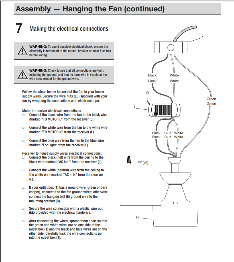
On the fan side in the wall there is a white (neutral bunch) and a red wire coming from the ceiling and the fan has a black, blue and white cable so a total of 5 cables. LZW36 fan controller only has 4 cables? So not quite sure what to do from there either. Here is a picture of the fan hookup as it is currently.
So it sounds like you have a 3-wire Romex going from your fan switches to the fan. This is pretty standard wiring. I’m presuming that you have two switches, one for the fan and the other for the light. The way it works is that that black carries the switched load for the light and the red carries the switched load for the fan (or vice versa). The white carries the neutral. In this configuration, the black will be connected to one wall switch and the red to another wall switch to individually control the fan and the light.
At the fan, the black and red are connected separately to the fan’s fan and light loads. The neutral is supplied for both, so they’ll all be bundled together.
The LZW36 works via a constant hot to the fan canopy module. That’s accomplished via a constant hot on the black. So in the switch box, both the Line and the black from the 3-wire go into the Line terminal on the LZW36. This provides a constant, unswitched hot at the fan canopy. You are not going to use the red conductor, so wire nut it to cap it off at both ends.
So at the canopy, you’ll connect the black coming from the switch to the black on the canopy module. This will provide the module constant power. The white will get connected to the neutral bundle of whites.
On the fan side, you’ll have a white, which goes to the neutral bundle, and two other wires, one for the fan and one for the light. You said you have a black and a blue. You’ll have to figure out which is which. The blue is probably the light, but that may vary by manufacturer.
What bothers me about your description is that it sounds like you have a 3-wire Romex at the switch box, but you didn’t mention a black from the 3-wire coming from the switch in the fan box. That doesn’t sound right. Obviously you don’t start out with 3 conductors and a ground on one side and wind up with 2 conductors and a ground on the other.
Maybe you can describe your original configuration switch/fan/light wise. There might be some pieces missing from your description.
Thanks for responding so quickly I will double check and get some additional pictures of what I see in the canopy as soon as I get some sunlight in the morning so I can turn the power off to the room.
Ok I think I figured it out to some extent. In the Box the two black lines were actually one line that used to be stripped in the middle and wrapped around a screw for the load wire. This line was snipped so it looked like two different wires when in all actuality it was one and the red wire in the box was the line wire. I pigtailed the two black lines together to make one wire and plugged the red and black lines into the switch. I was then able to follow your directions for the canopy and once everything was squared away and after excluding the device I was able to get everything working!! So far this switch is awesome! Thanks for you help @Bry