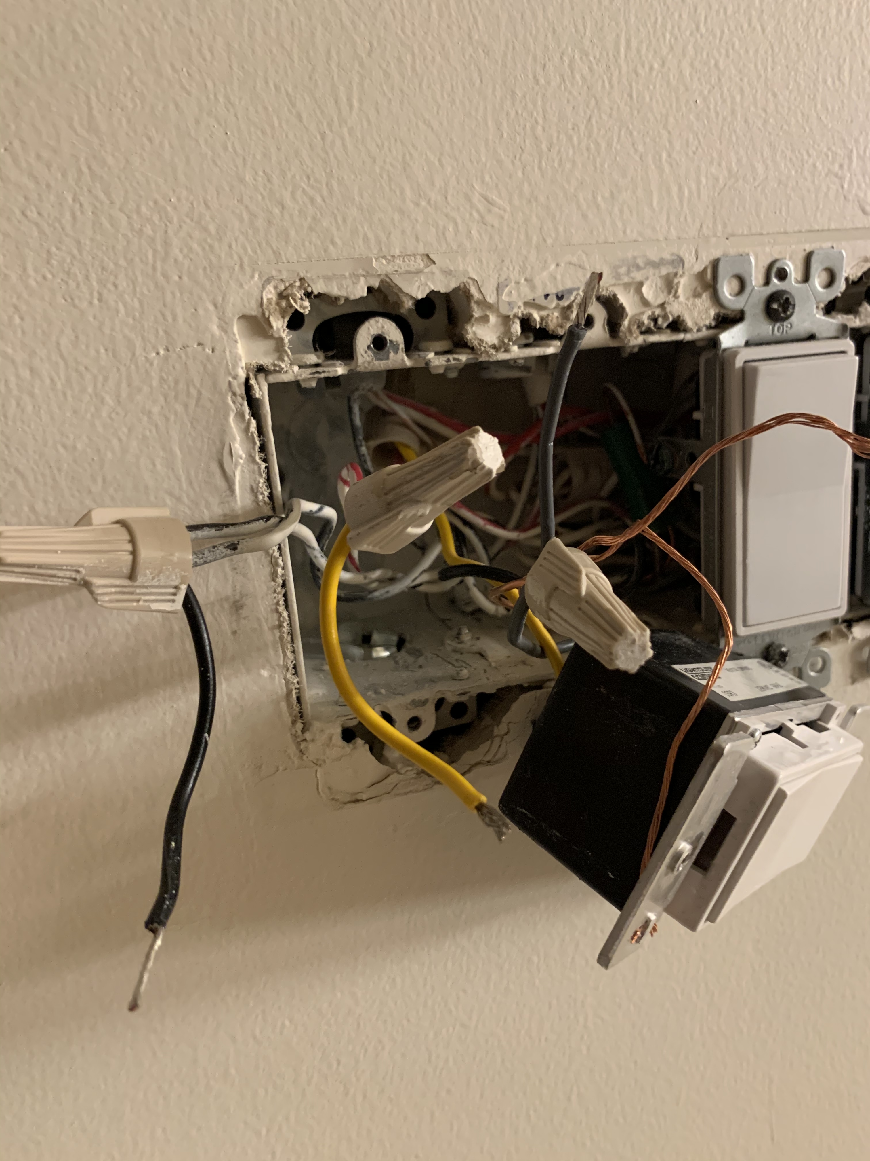
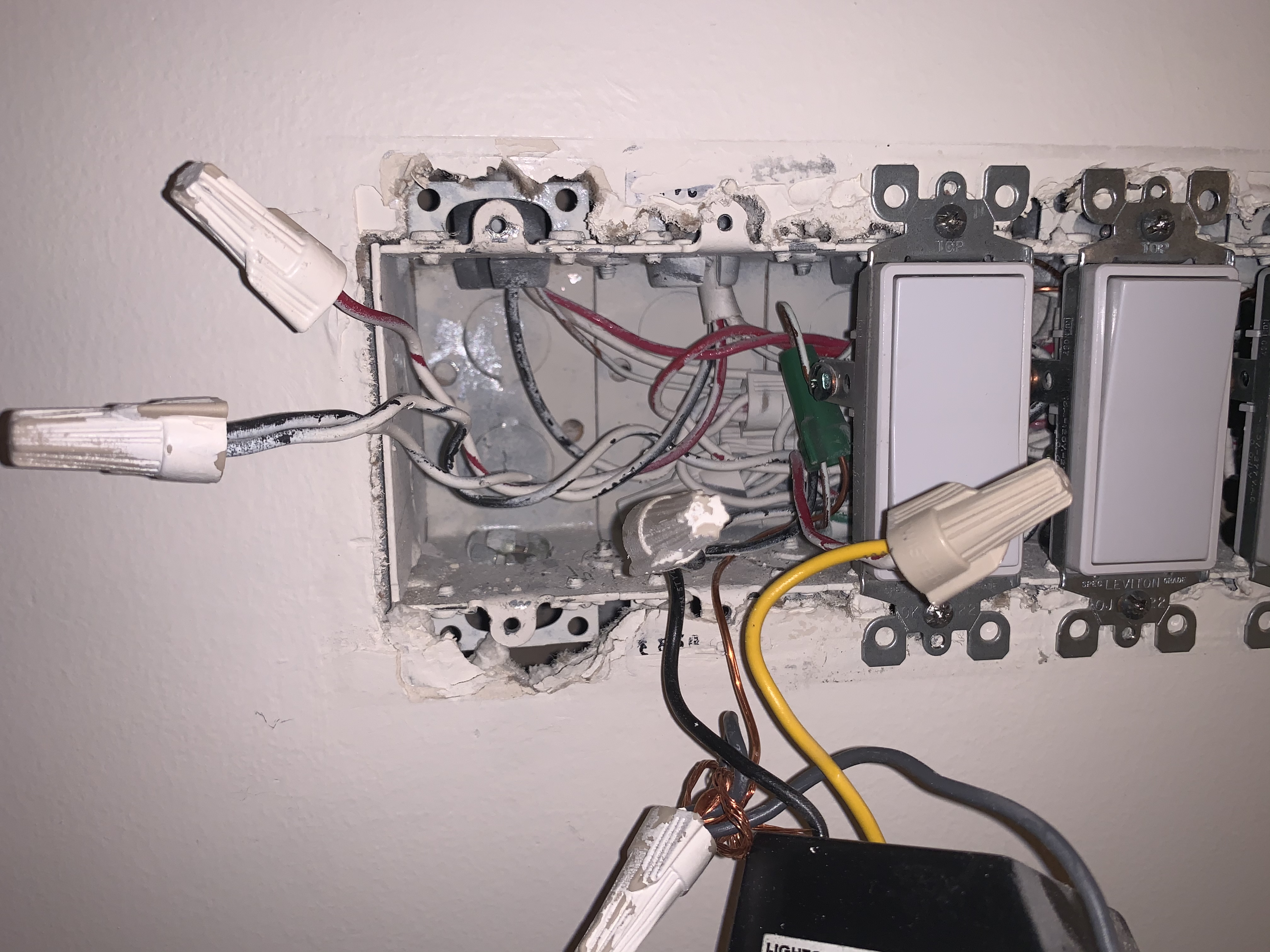
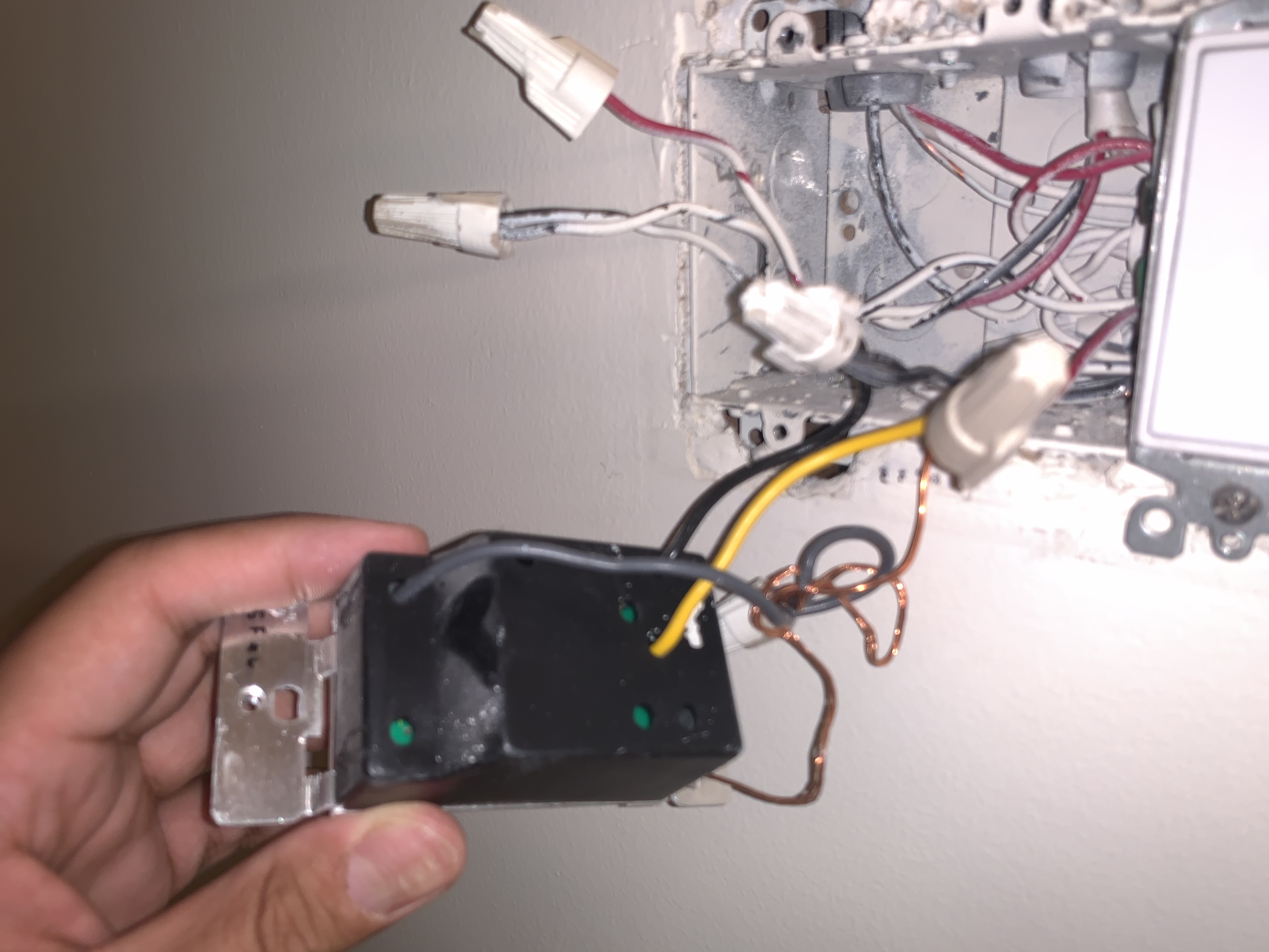
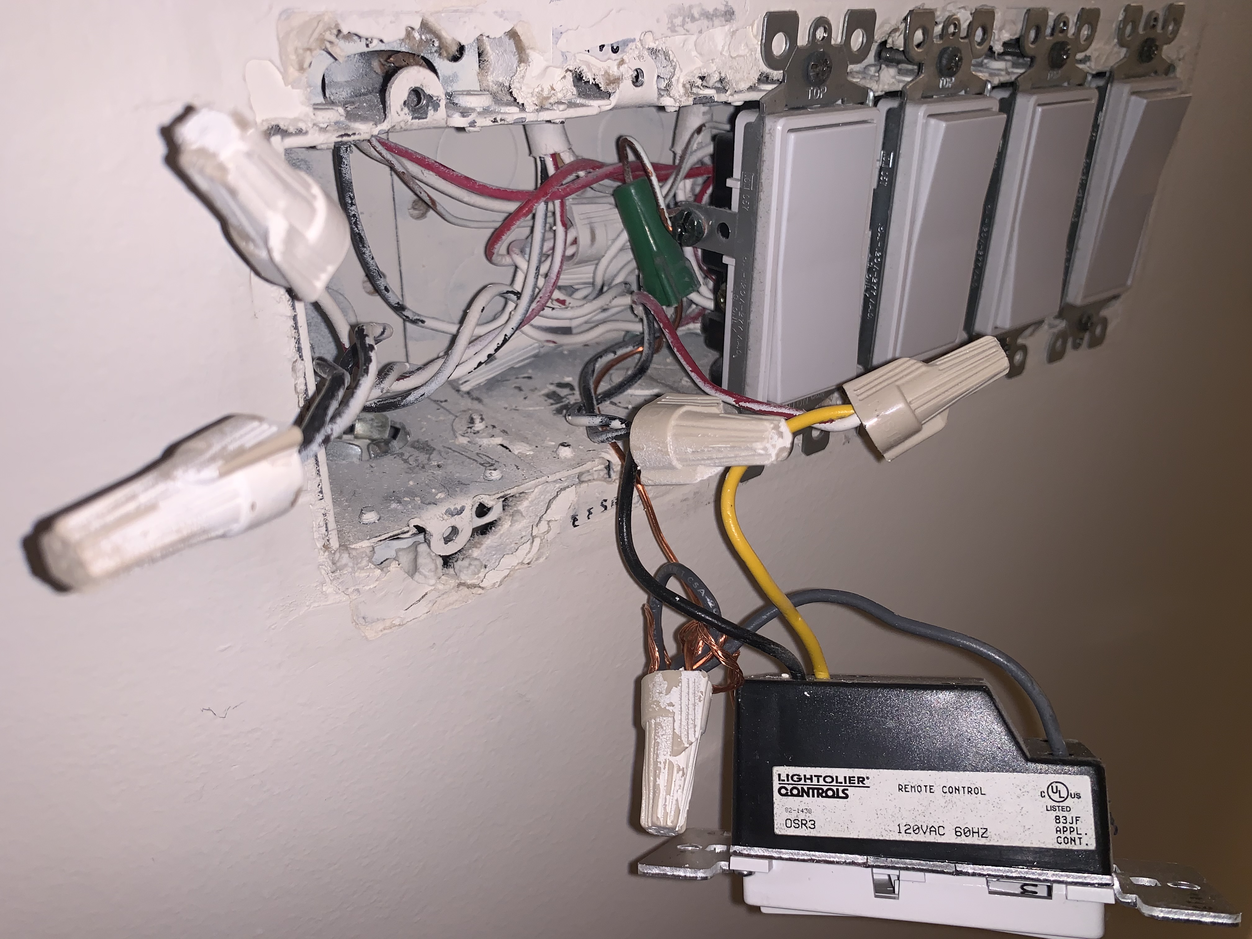
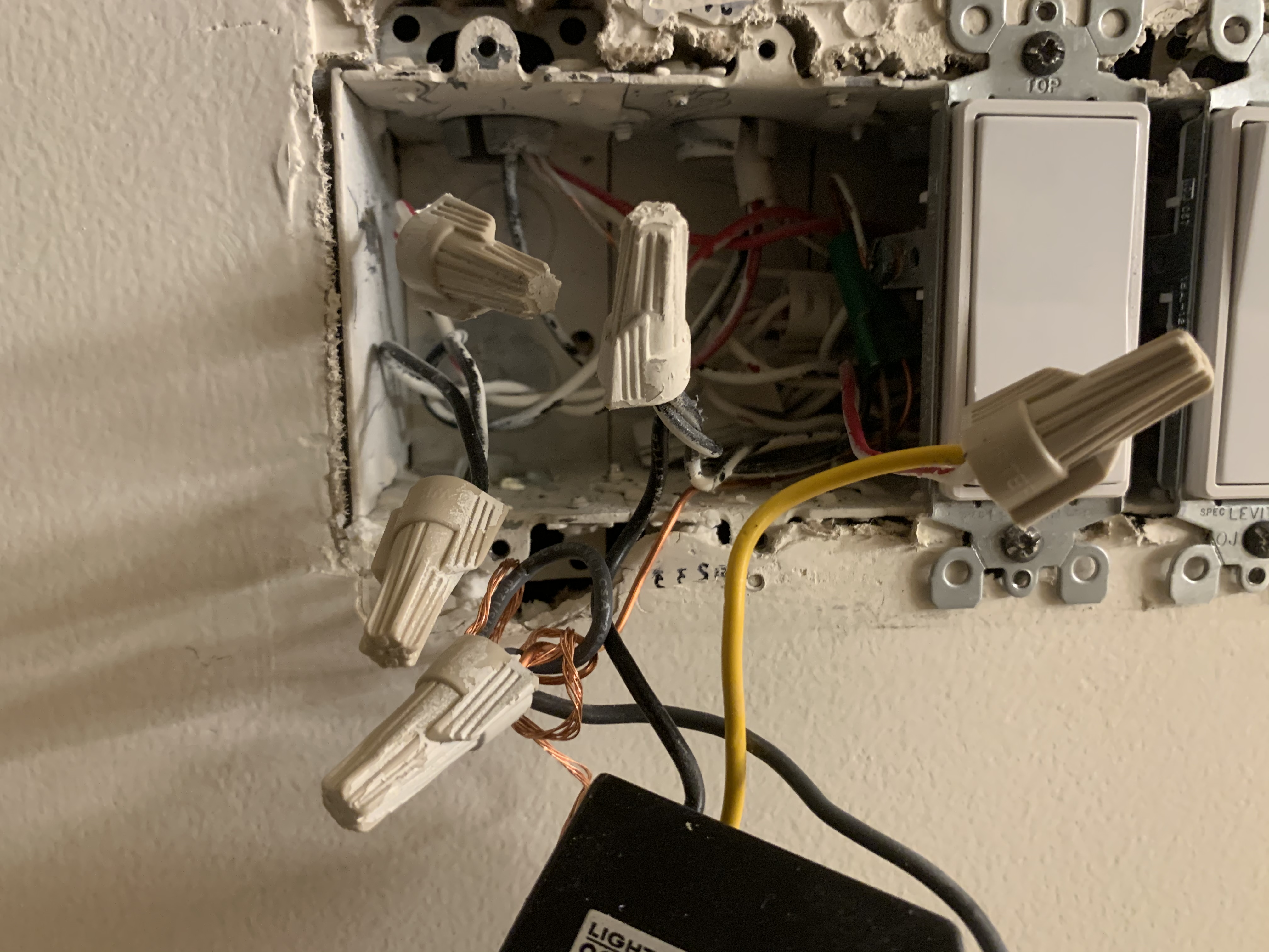
Thanks for posting the extra pictures, but at this point it’s just a mess of pictures. I THINK you posted pictures of the other box, but I can’t tell for sure. Plus what I THINK is the other box has two switches removed from the box so I’m not sure in which slot or with which cables are involved with this switch.
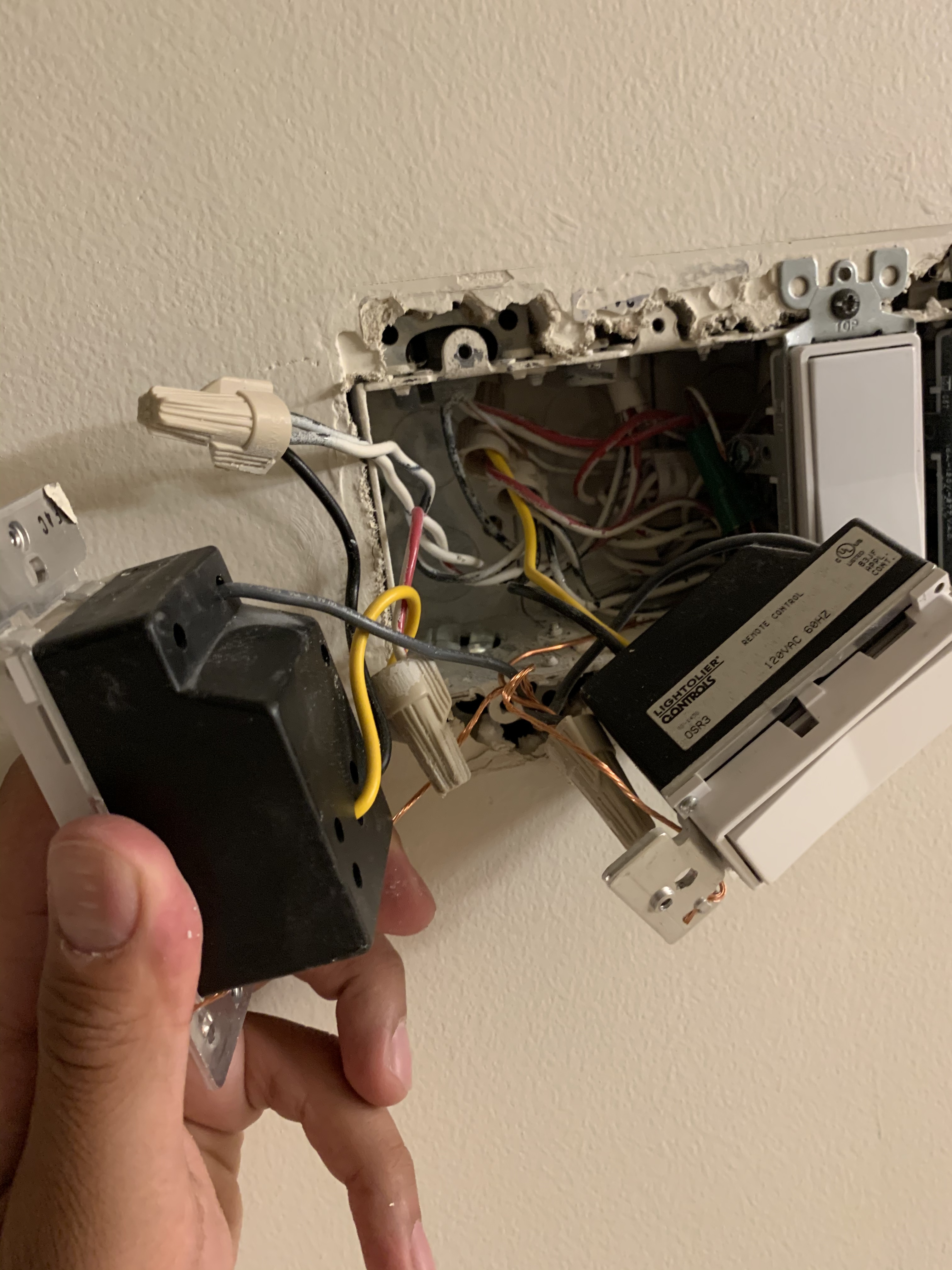
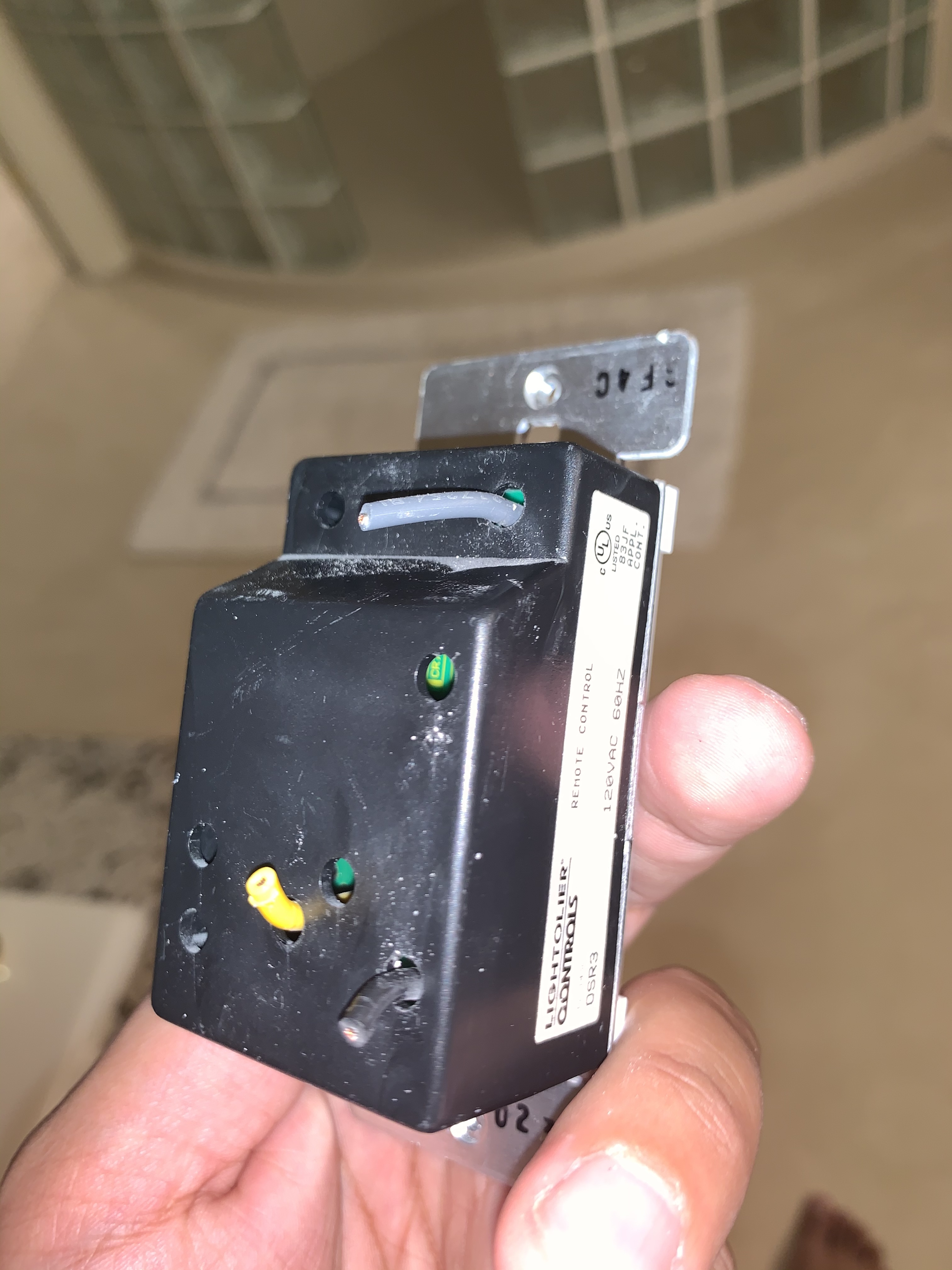
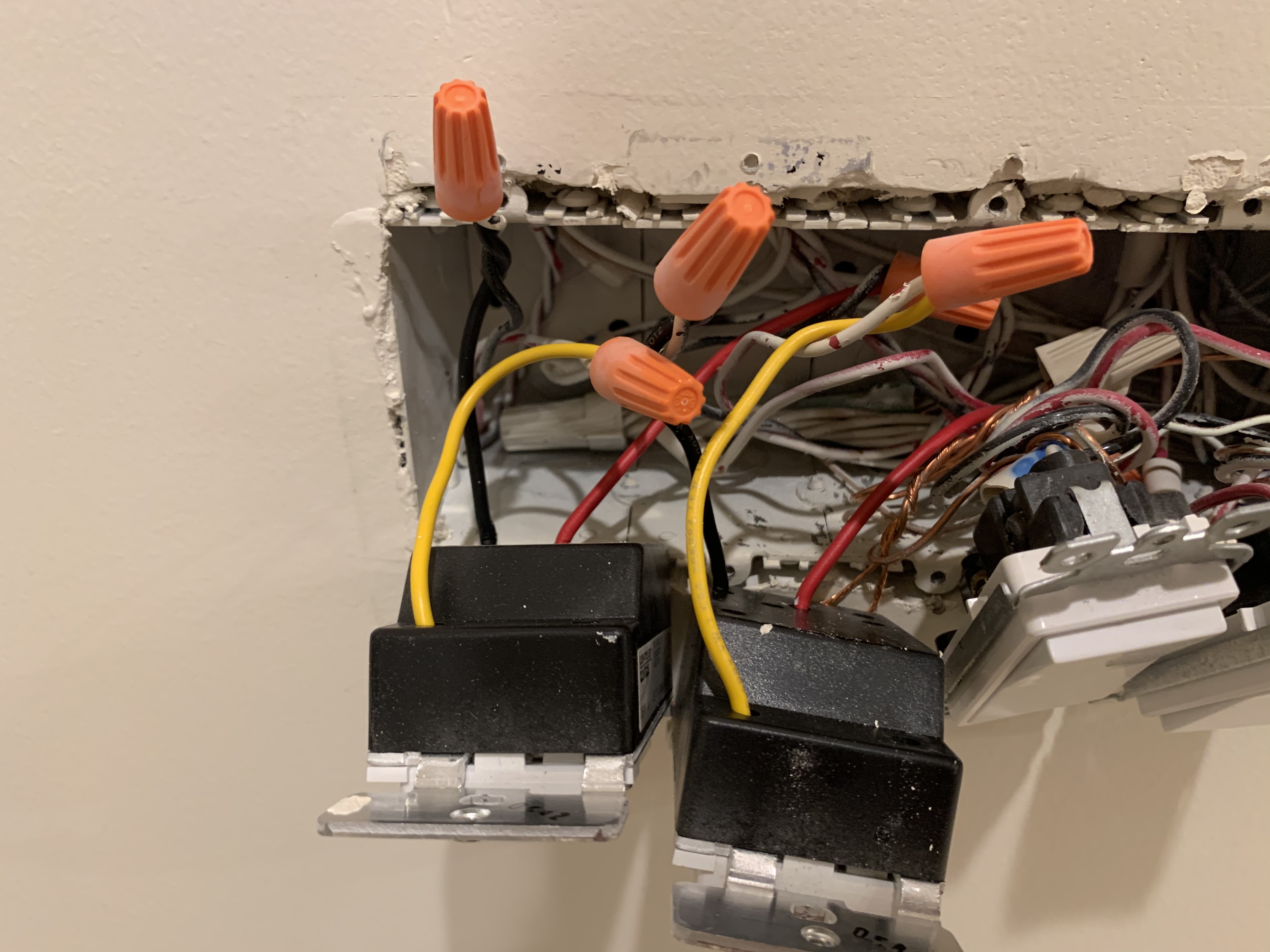
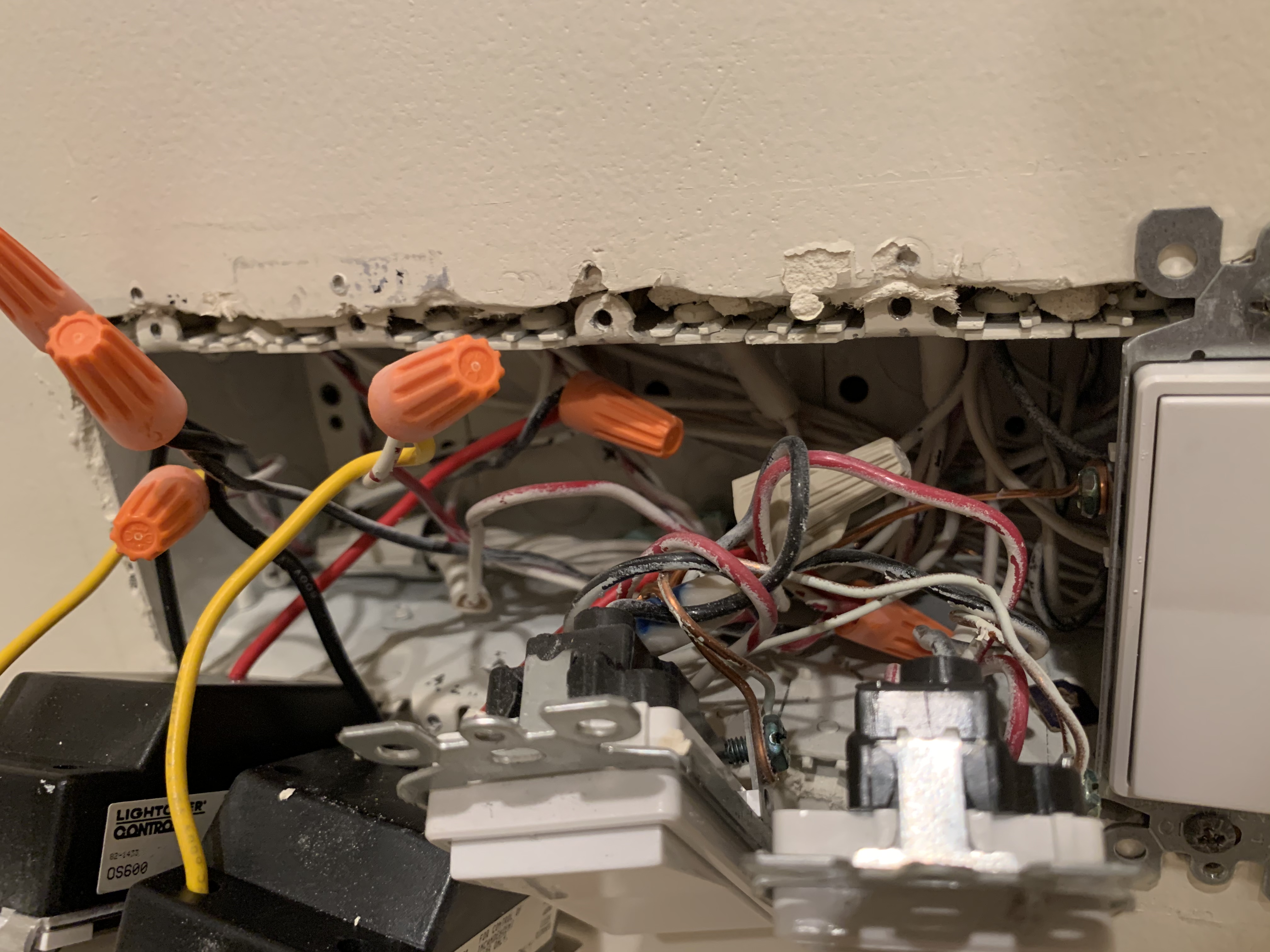
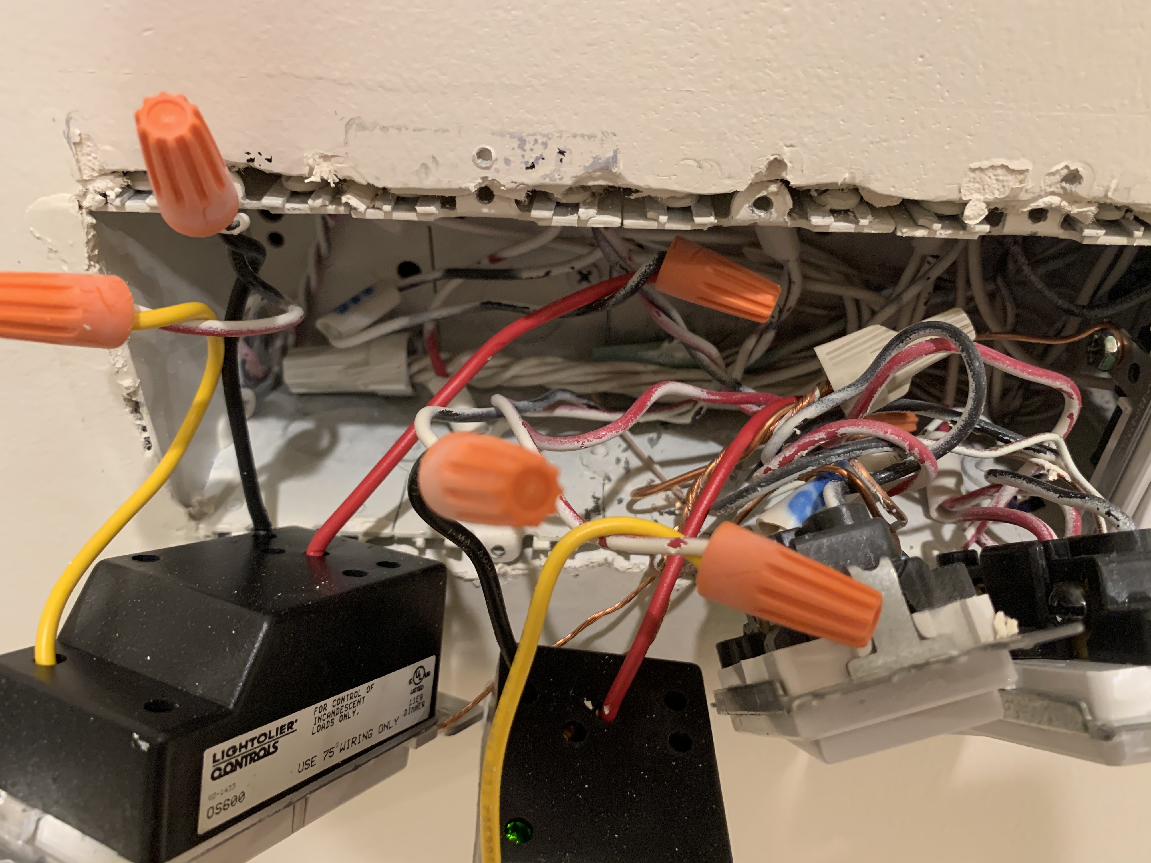
So . . I’ll get you started in another way. The existing switches, based upon a label in the first pics posted, are Lightolier Onsets. They were discontinued in 2013 but the manuals are still available.
The Lightoliers work with a main dimmer and a remote unit, sort of like an Inovelli and an aux. Looking at the wiring schematics for the Lightolier, it appears they need a line and load in the same box, with a hot and a traveler to the remote switch.
The pic of the switch you posted first is a OSR-3 remote unit, so the main dimmer is in the other box. The Inovelli will have to go in the box where the main dimmer is.
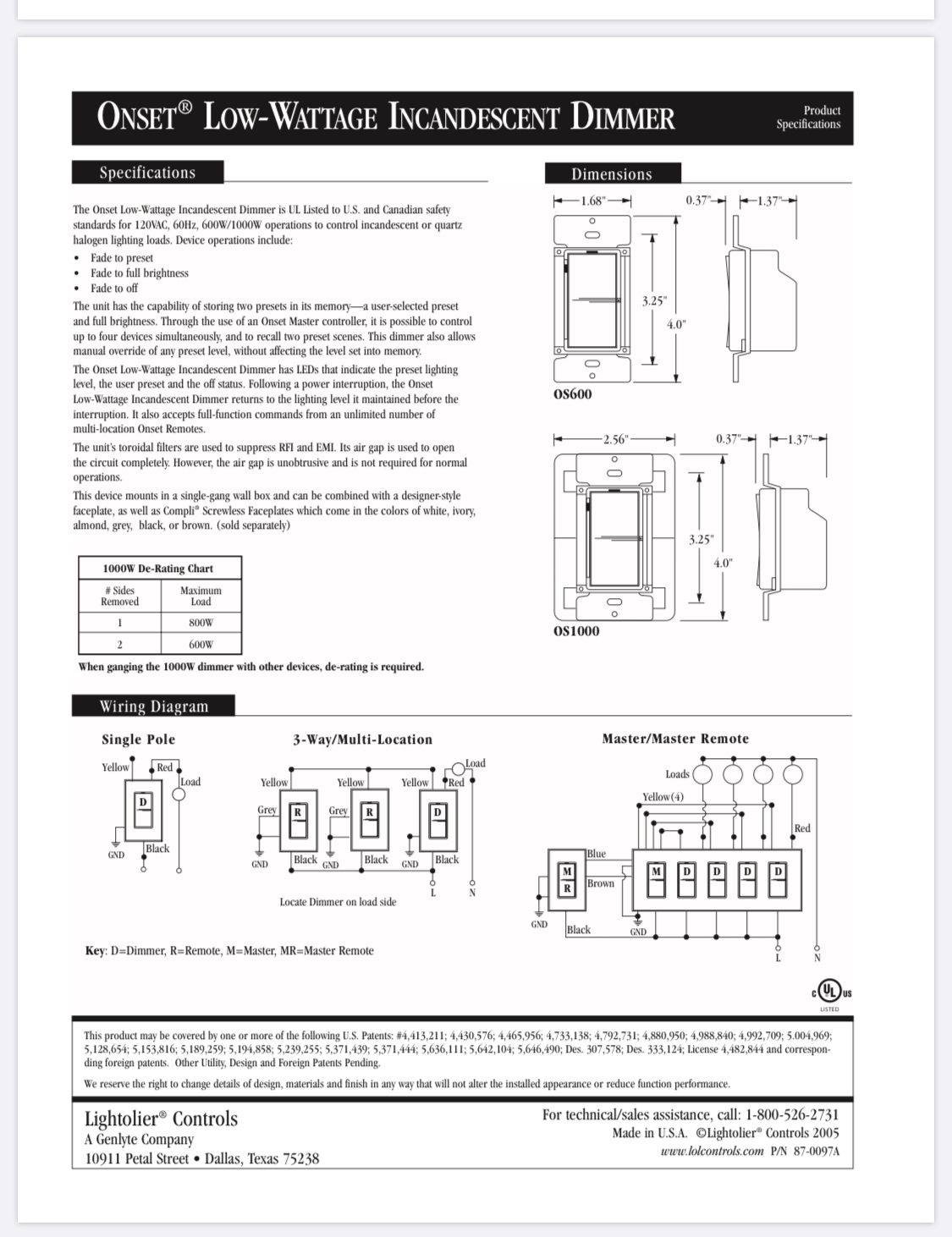
I’m not sure which exact model dimmer you have, but believe their wiring configuration will be about the same. I’d suggest you figure out your wiring from analyzing the connections to the main dimmer.
Looking at the wiring for an OS 600, the red lead goes to the Load, the yellow lead goes to the traveler (which might be red for you) and the black lead goes to the Line. It’s also connected to a conductor (probably black) that goes to the remote box.
So as far as I can tell, you’re starting in the wrong box, which is why you thought you had a non-neutral. The Inovelli goes in the box where the main Lightolier dimmer is, and an Aux goes where the Lightolier remote dimmer is.
That’s about the best I can do at this point, as TBH, it’s impossible to determine more from your pictures without same labeling and identification. No guarantees I’m accurate, but this is my best guess based on what I’m seeing.
http://plc.philipsnas.com/discontinued-onset
http://plc.philipsnas.com/assets/cms/uploads/files/discontinued/onset/ig/85-6286.pdf