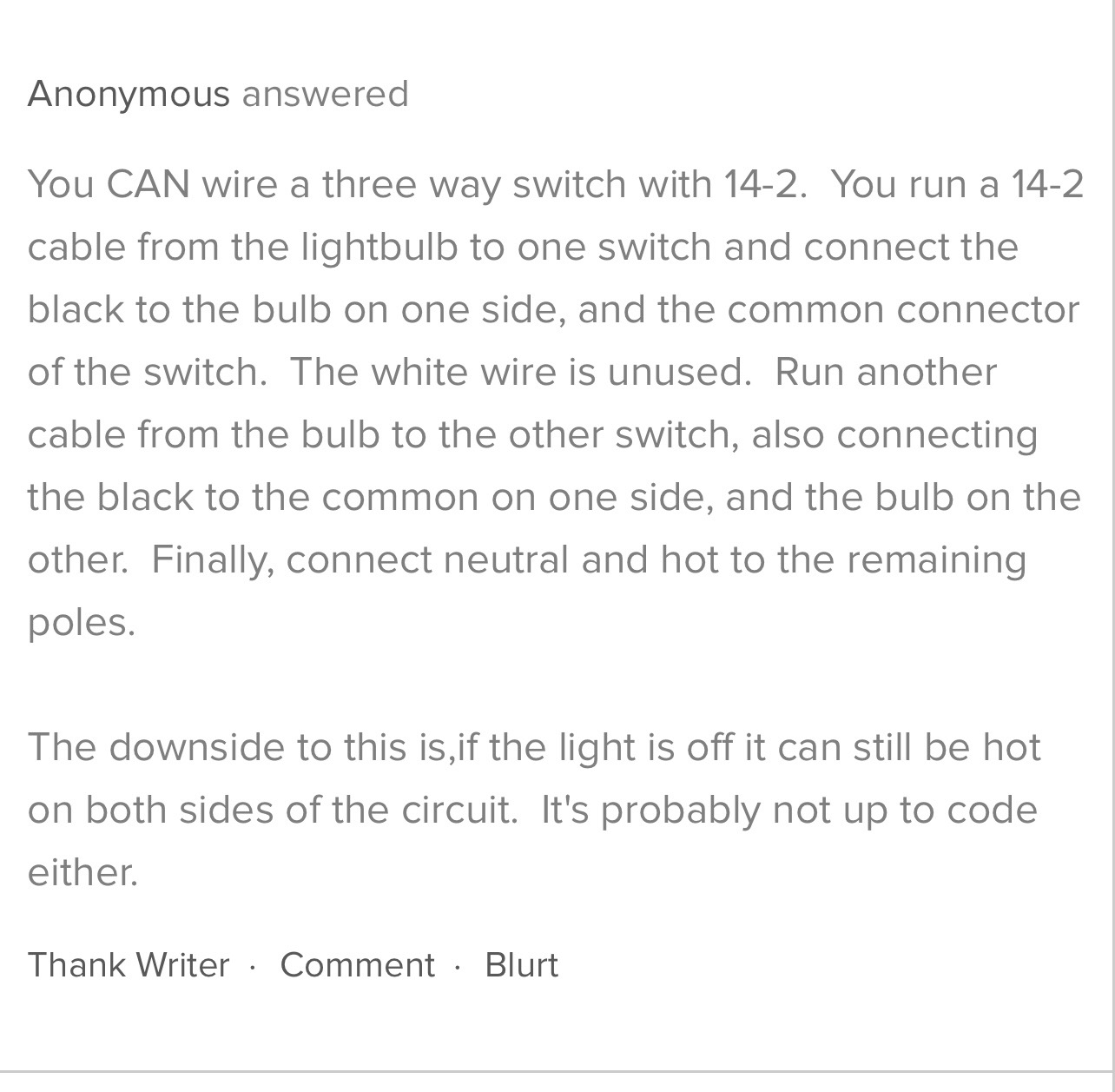
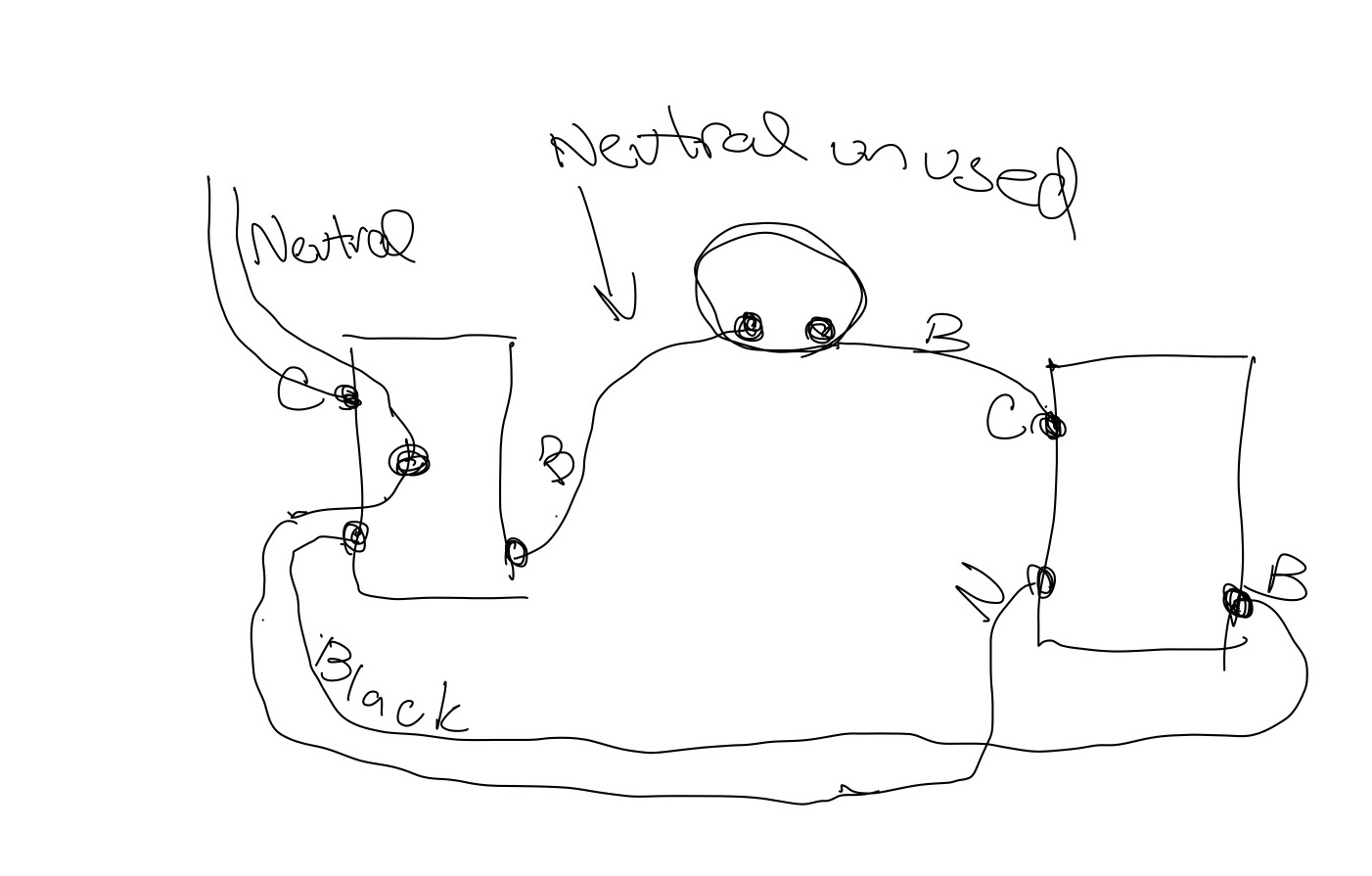
My house was wired around 2005 and I am trying to figure out how I can get this 3 way switch to work, ideally with 2 Blue 2-1 smart switches but none of the diagrams match up how this thing is setup. The three way switch was wired up using 12-2 wiring so there are two 12-2’s between switches where one of them only uses the black wire and the neutral is capped off on both sides. The other 12-2 connects between the two switches. I’ve attached an explanation I found that does a good job of describing how it is wired up. And also my best attempt of drawing this out. I left the grounds out to make it easier to see
Can someone tell me what is possible here? I can only see the 12-2 that is unused in the junction box for the light the other must be travelling outside of it.
I think the answer is somewhere in this diagram but I’d need to test and don’t want to jack up the switch. Essentially the white wire on the light would become the black wire in my diagram as the neutral to switch is not used. then rather than the blac going between switches being a load it would be the line. this giving me the power I need for the 2nd smart switch but I feel like somehow I’m missing something.
2 conductor from left box to right box, these would be the traveler wires
2 conductor from each box to the light.
I think you want to wire
the neutral from the power romex to the white of the romex going to the light from the left box and to the white of the romex going to the other switch. Connect the white to the neutral terminal of both switches and to the neutral of the light.
The live from the power romex to the black wire of the romex going to the other switch box. Connect it to the line terminals on both switches.
Connect the black of the romex in the left box to the load on that swtich.
Cap off both wires in the romex going from the right box to the light at both ends.
The left switch will control the light. The right one is just a controller now, you use it to control the left swtich.
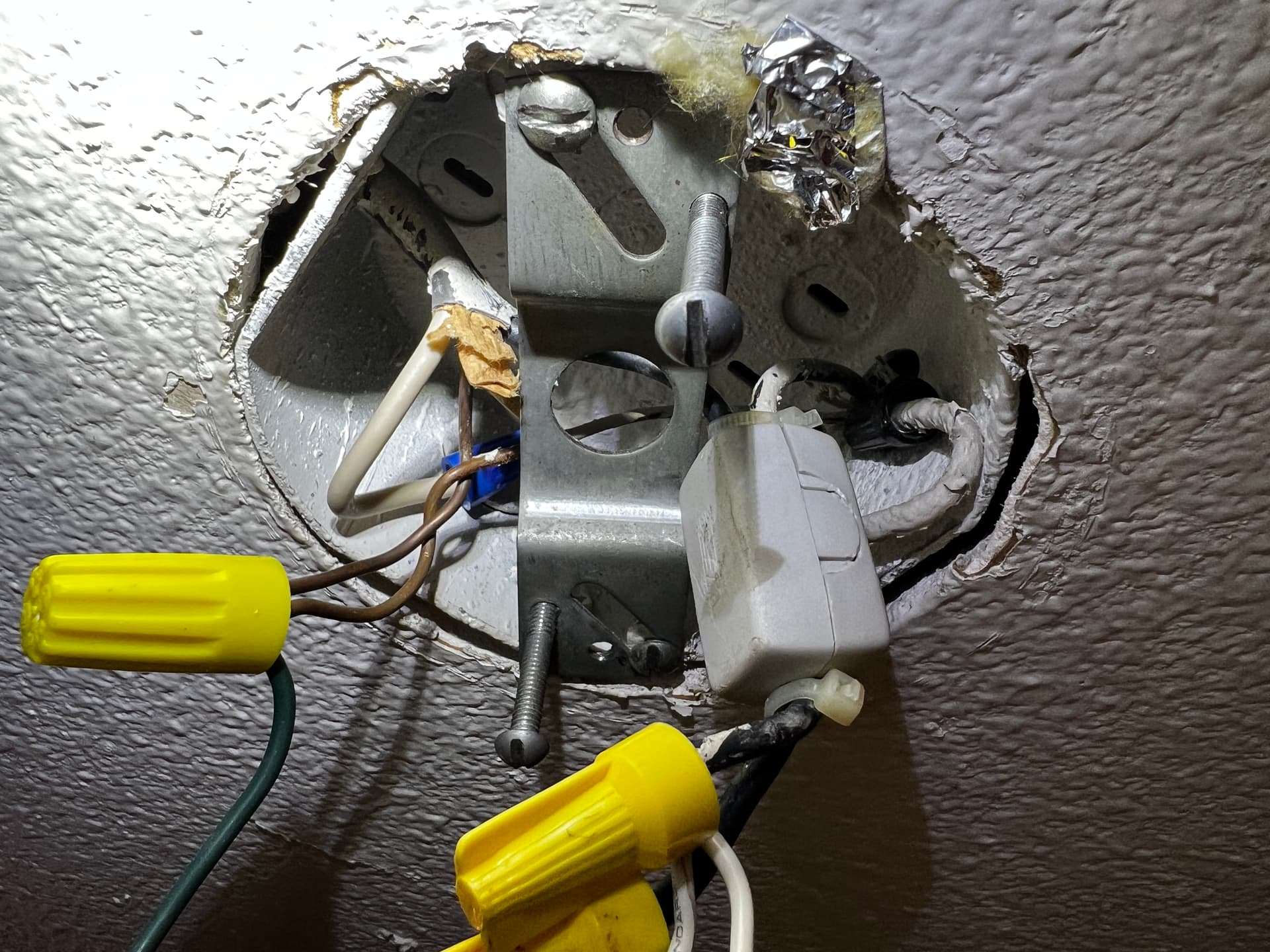
Thank you that makes total sense. I pulled the light down to make the changes and I noticed this component clipped around the two blacks feeding the light. Did some googling and it’s a ferrite core from Wurth Elektronics.]([74271111 Würth Elektronik | Filters | DigiKey])
Here’s a pic of how it’s used:
So with the exception of not knowing if I should keep the ferrite core around the wires I got it all up and running. Thanks a ton! Im gonna go with the core is not needed unless I see weird things or someone here knows something!
One other question. What would I set the Aux Switch type parameter for each of the switches. I imagine the Main switch controlling load would be no aux and the other switch just being powered would be smart aux?
You don’t set it to any aux mode. It’s just a switch without a load. You can group it to the load switch and then it will directly control the load switch. I’m not positive with Zigbee but you might have to group the load switch to it as well so it stays synchronized to the load switch.
Awesome, that’s what I ended up doing. Everything is all synced at this point. I even changed the 2nd switch to control a larger set of lights! I finally can turn on my kitchen lights without having to say Hey Google or Alexa!! No more tape on the switches and my kid, who HATES talking to the assistants thinks I walk on water now!