I’m struggling to set up my new Inovelli Blue Dimmer switches, and looking for some assistance. Please forgive me if I miss some necessary information, as I’m no expert in electrical work.
I have a 3-way switch setup in my basement. I live in an area that requires grounded conduit in residential homes, so no ground wires. There are two boxes I’ll refer to here:
The first is Box A, which has a hot wire (black), and two other wires (dark red and brown). There is no neutral wire present in this box.
The second is Box B, which has a yellow wire, dark red, and brown. There is also a neutral wire in this box that can be used if necessary.
I have a Blue Dimmer switch that I’d like to set up. I also purchased an Inovelli White (Aux) switch, as I was told this would assist in a non-neutral wire setup. I believe the non-neutral setup is necessary because I only have a neutral wire in Box B, which does not contain the hot wire.
My understanding is that the Blue switch will need to be installed in Box A, since that’s where the hot wire is. I’ve attempted several wiring configurations with the Blue switch in Box A and the Aux switch in Box B, however no matter what, the lights will not turn on and the RGB indicator light on the Blue switch does not turn on.
Would someone please be able to help me troubleshoot my setup to see if it’s compatible with a Blue + Aux switch setup without a Neutral wire in both boxes? Electricians are rather expensive in my area because everything’s in conduit, but if all else fails I could have a neutral wire added to Box A.
I have also included some images of my “dumb” switches installed before I modified anything. Box A Box B
Quick update: I was able to install the Blue switch in Box B (no neutral wire) and have it power on. However, if I use an Aux switch in Box A, neither switch works, and the lights are off. My temporary solution was to reinstall the “dumb” switch in Box A. This allows the Blue switch to power on most of the time, but if the dumb switch is flipped, then the Blue switch loses all power and functionality.
Is there anything I can do to get my setup working without adding a neutral wire to Box B? I feel like this should be possible with the Aux switch, but nothing seems to be working.
The problem contributing to the lack of responses is that you have THHN/THWN conductors run in conduit. That makes it much more difficult to discern the connections than it would be with Romex. I would guess that in your area, electricians commonly use certain colored conductors for certain applications, even thoough the electrical code doesn’t necessarily specify color codes to that extent. Without that knowledge, understanding the connections is even harder.
If you have enough electrical knowledge to be able to trace and draw out the connections, then we can draw a solution.
If it helps, with a non-neutral 3-way, there are two common wiring configurations. Both have power to the light in common, hence the non-neutral. I can’t tell from your pictures if you really have a non-neutral, but if you do, this may help.
The first has a 3-wire (3 conductors in your case, exclusive of the ground which you don’t have because you’re in conduit) going from the light to the first switch box and then a 3-wire (3 conductors in your case) going from the first switch box to the second switch box.
The other has a a 3-wire (3 conductors in your case) going from the light box to each of the two switch boxes.
Thanks so much for your response - I think this is a classic case of “I didn’t know what I didn’t know”, so I appreciate you taking the time to point me in the right direction. I did a little digging today and found the two access boxes in between the switches. Each of these access boxes split off into flexible conduit attached to can lights.
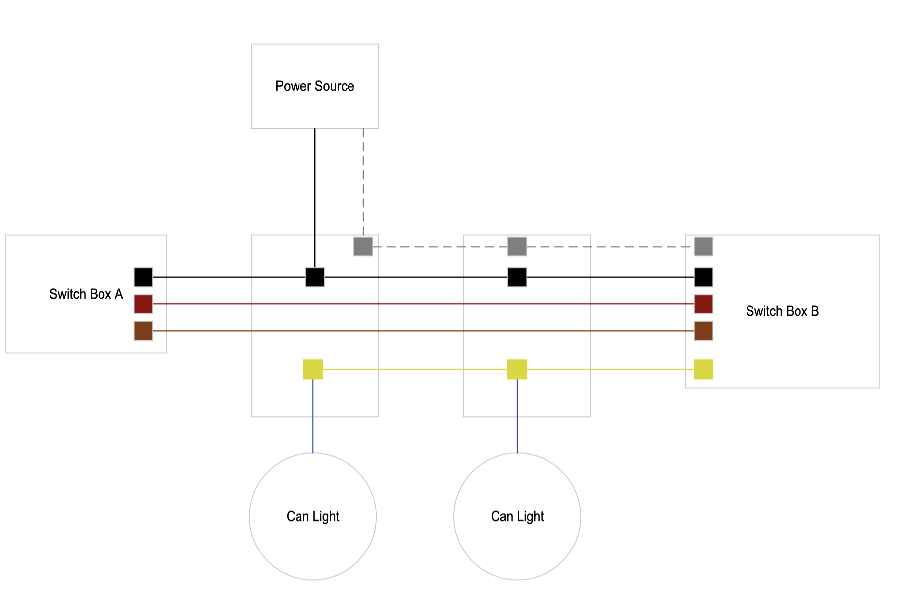
Here’s a drawing of my setup, to the best of my ability. Please note, I left off the neutral wires for simplicity - the neutrals are present in all boxes except Switch Box A. Let me know if it makes sense or if you’d like me to explain further!
From the scenarios you described, I believe I have the second setup. The hot wire goes to the light box first, and then to each of the switch boxes from there.
I appreciate the simplicity, but I’d like to see the neutrals in the drawing. Use black for hot and grey or dotted grey for the neutral. I also need to see the connections of the conductors.
Thanks. That is what I was looking for in the way of detail. Unfortunately, I don’t believe your drawing is accurate, The connections don’t make sense from an electrical perspective.
A couple things that I see that don’t make sense:
There needs to be two conductors to the lights. They need a hot and a neutral to work
You have the hot going to both switches. In a typical 3-way, the hot is is routed from the source to only one of the switches, where is is passed to the other switch over one of the two travelers. The common screw on the “far” switch then feeds the hot to the bulbs.
Even if the hot is in the “far” box and the yellow is connected to the common terminal on that switch as the switch hot to the light, I don’t see how the neutral makes its way to the bulbs.
It might be best for you to consult with an electrician to get a good understanding of what’s going on. It’s just really tough to diagnose the individual connectors without the use of tools to conduct the tracing.
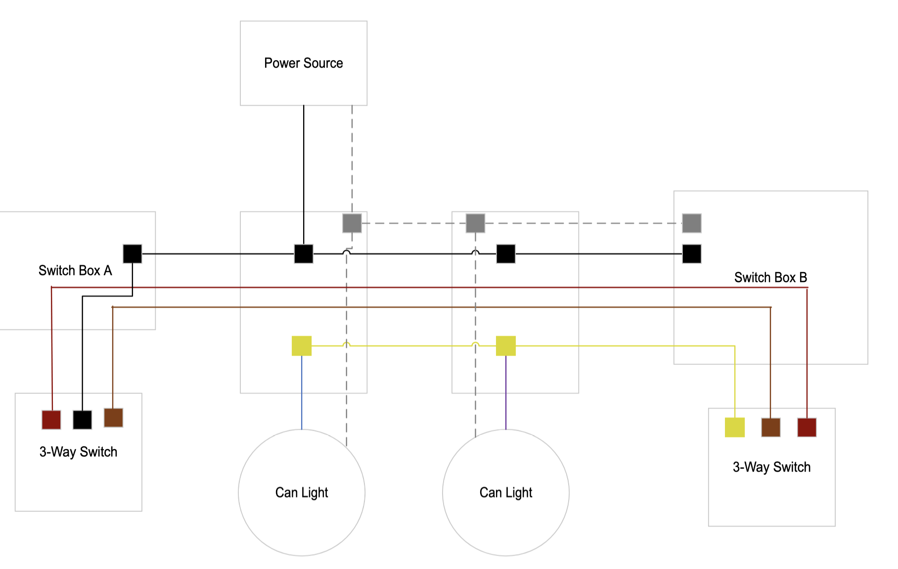
You are definitely correct - my last drawing was not accurate. I forgot to add the neutrals going to the can lights - I double checked and they are there. Additionally, I misrepresented the hot wires in Box B. There is a hot wire present in that box, but it goes to another switch, not the 3-way one in question. The hot wire is connected to the common for the switch in Box A, and the yellow wire is connected to the common in Box B. I added switches to my diagram to make this more clear. Does this look more correct to you?
Here is the quick description. I can draw it out if need be.
This is a non-neutral with the Inovelli in Box B. Box A is an Aux switch. You may need a bypass at the light.
Box A - Aux Switch:
Hot conductor to the Neutral terminal of the Aux. Connect one of the two travelers to this terminal as well. (I don’t remember if there are 2 holes or if you will have to pigtail.) This will send the hot to the other box.
Connect the other traveler to the Traveler terminal on the Aux. This will send the traveler to the other box.
Box A - Inovelli:
Hot conductor coming from the Aux box to the Line terminal on the Inovelli.
Traveler conductor coming from the other box to the Traveler terminal on the Inovelli.
Yellow Load conductor to the Load terminal on the Inovelli.
On the Inovelli, you will need to set Parameter 22 (Switch Type) to 2 = Multi-Way (Auxiliary Switch). The switch will auto-detect the non-neutral, so there is no need to set that.
Thanks so much for these instructions! That wiring definitely makes sense, I don’t think a drawing is necessary, but I appreciate that!
Question for you before I start wiring up the switches - Is it possible for me to install the Inovelli in Box A, and the Aux in Box B? I’m assuming it’s not, but just want to double check, as that would be my (or rather, my spouse’s) preference for usability.
Ordinarily, you wouldn’t have enough conductors, but in your case, this might work since according to your drawing, you have a hot from the same branch circuit in each box.
Box A - Inovelli
Hot conductor to the Line terminal on the Inovelli.
One of the travelers to the Load terminal on the Inovelli.
The other traveler to the Traveler terminal on the Inovelli.
Box B - Aux
Conductor from the Load terminal on the Inovelli to the yellow Load conductor to the lights.
Hot conductor to the Neutral terminal on the Aux.
Conductor from the Traveler terminal on the Inovelli to the Traveler terminal on the Aux.
On the Inovelli, you will need to set Parameter 22 (Switch Type) to 2 = Multi-Way (Auxiliary Switch). The switch will auto-detect the non-neutral, so there is no need to set that.
So you are basically passing the Inovelli’s Load to the other box to route to the lights. If you didn’t have a hot in Box B, you’d be short one conductor because you only have two unused conductors.