I found a few threads dealing with switched outlets, but I didn’t find any mentioning non-neutral switched outlets which presents a few problems. Most notably, you have the same issues you have with a non-neutral light fixtures with an LED in that they need a bypass to work. I’m listing a few solutions below (posted this on a Facebook smart home forum as well), my main question here is… Can I wire an Inovelli Red switch with just line, and neutral, no load? This assumes I’m disabling local control and using the switch as a remote control (see solution 2), here’s my original post:
Non-neutral switched AC outlet solutions.
So, I have a switched AC outlet. Line goes to the outlet, not the switch, so the switch has no neutral. I have a lamp with an LED bulb connected to it. You can see where this is going. I’m going to use an Inovelli Red switch on the outlet with the ramp times set to zero as while I could put a dimmer on an outlet… that just fundamentally bothers me.
Here’s the solutions I can think of:
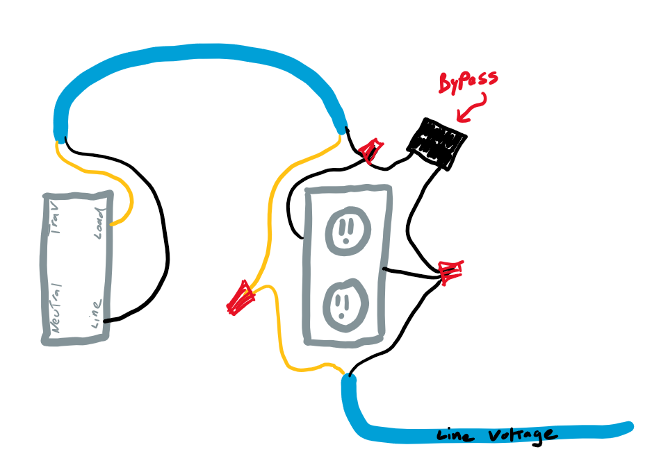
Put an Aeotec Bypass across the line, and the neutral at the AC outlet. (modifying the lamp makes no sense… if I installed it in the lamp that would work fine BUT… that would be the ONLY lamp I could use with that outlet, if it failed I couldn’t grab another lamp (with an LED light in it) and use that))
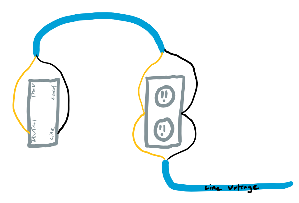
(this one is my favorite idea so far) Pigtail line and neutral, and send that to the switch box. In this configuration the outlet is not switched and always has power. The Inovelli switch would then be connected in a neutral scenario, it just wouldn’t have a load connected to it. I could disable local control on the Inovelli switch essentially making it a remote control which could then control a smart plug. I kind of like this solution because then it detaches the lamp from any particular outlet, I don’t have to worry about having an outlet that can only handle 400 watts. This is also the cheapest solution as I already have an Iris outlet that I’m not using. I’m running a Hubitat so control is local and the switch would still work even if my ISP goes down.
Get a Z-Wave outlet and install that, disable local control in the switch, and then have the switch tell the outlet via Z-Wave to turn on or off. I’m working under the assumption that the switch can draw enough current to do its thing since a smart outlet also needs to draw a bit of current to work, but won’t output that since the outlets themselves are isolated on a relay.
I dont think this would be a problem. Functionally, it would be the same as wiring it up to a light fixture, but removing the bulbs (the load wire doesnt actually do anything if there are no bulbs).
I dont think it would work that way. You need 3 wires to the switch (Line, Neutral, and Load). If you put a bypass at the outlet, you still only have 2 wires at the switch itself (you are talking about a switch, and not a dimmer, right?)
This is what I would probably do (since it sounds like you already have the hardware). The would need to be a red switch though (for scenes), and your hub would then communicate with the Iris. I am not an electrician though, so I cant confirm whether this is to code or not.
This would essentially be a modification of #2 above. You need a Line and Neutral to the switch (no load), and the outlet would also need Line and Neutral. Associate the switch with the outlet, and you should only need to worry about the load requirements on the outlet itself (since there would be no load on the switch).
It’s the Red dimmer. None of the switches work without neutral so those would be a non-starter. In theory I don’t think the Aeotec bypass on the outlet would be any different that it would be when installing it into a light fixture. As far as drawing out a schematic goes, (including the plugged-in light as part of the circuit) I think the wiring would be identical to a non-neutral switched light fixture.
Actually I was thinking about it a little differently, wiring it in a non-neutral configuration with line, and load, and hoping that the electronics required to drive the “smart” part of the outlet would provide enough draw to keep the Red switch awake in a non-neutral line/load configuration (the local switch would essentially be in the “off” position, with local control disabled)… but duh… If I’m going through the trouble of doing that, it makes more sense to do the solution 2 implementation (which is cheaper, and less work for me).
Thanks. If anyone knows if solution 2 would meet code, I’d love to know, otherwise I could cap then ends and use a battery powered remote.
To visualize it, just replace the light fixture in this diagram (which would have the bypass installed between neutral and line at the light fixture) with an ac outlet. When you plug the lamp in, the circuit is essentially identical to this one:
With this setup, you dont need a bypass, and you could use either a red series dimmer or red series switch (it would need to be red series to work with your Iris outlet though because your hub would need to process the scenes and relay the message).
If you use the same setup as above, but also replace the outlet with a zwave outlet, you could use a red or black series switch and directly associate the devices (less lag and no true reliance on the hub)
That is good code-wise. You not doing anything more than sending that circuit downstream to the next device. If you do that and you’re planning on using it with a pocket socket, I’m thinking you should be using a switch, not a dimmer. If you are going to use this with a lamp you want to dim, then I’d probably keep the lamp powered up full time and use the dimmer switch and a smart bulb. Or use a pocket dimmer, but they’re getting hard to find.
Although the 2017 code carves out an obscure exception if you use a special receptacle/plug combination that only allows that special plug on the lamp to be plugged into it. I’m not even sure those receptacles/plugs are available.
I’m trying to do something similar, though not to an outlet as an end, but to just a fan fixture. The main goal is to have smart bulbs in the fan, like the kids’ room, but not to disrupt power to them each time by physically removing power. I’m fairly new to inovelli and to non-neutral scenarios, so if I’m doing something incredibly dumb that isn’t similar to this thread, then apologies ahead of time.
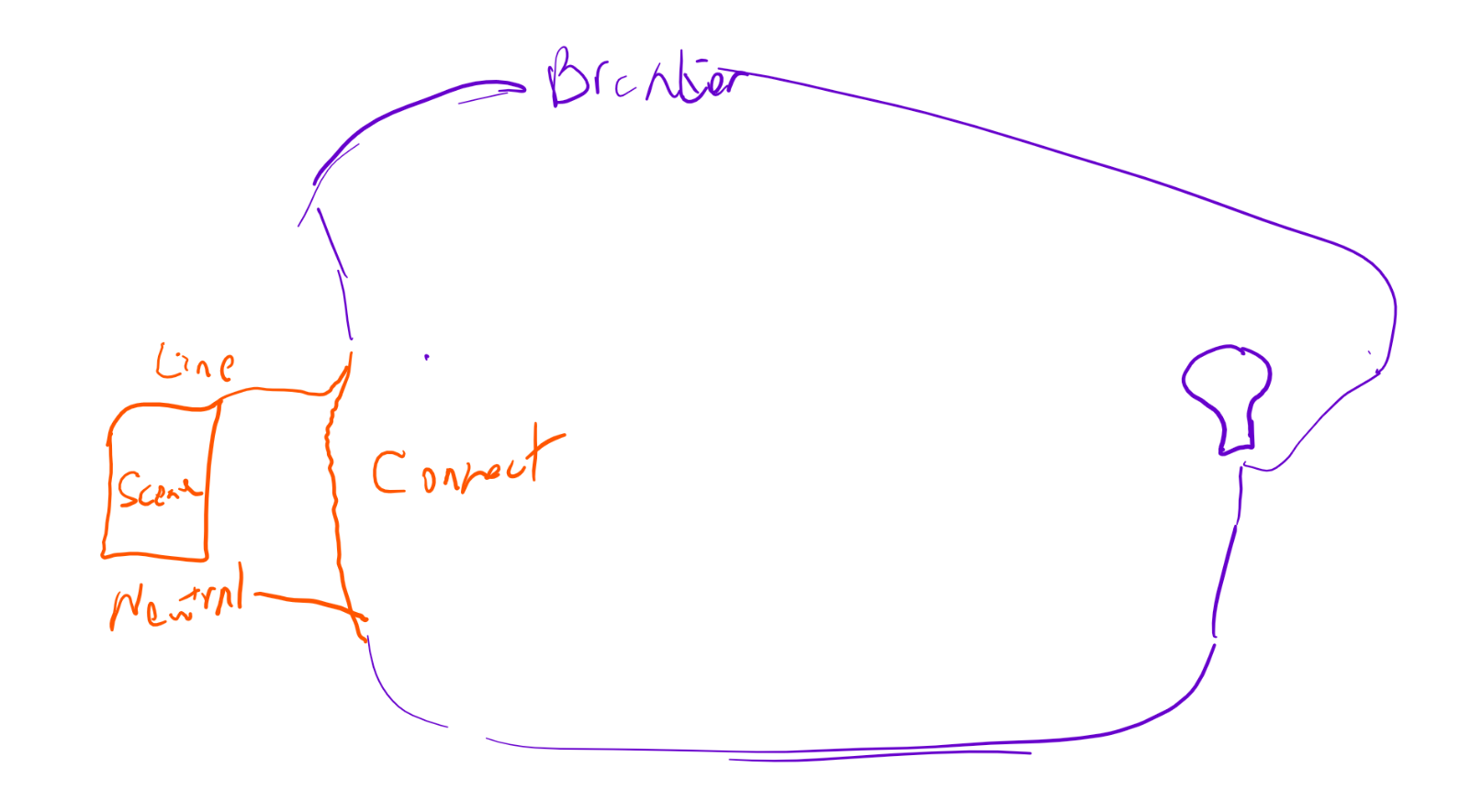
I thought I would connect the line and load together, and then use the inovelli red as a pure scene controller.
The inovelli red just has the line and neutral, and no load attached. However, there appears to be no power at all to the inovelli switch like above.
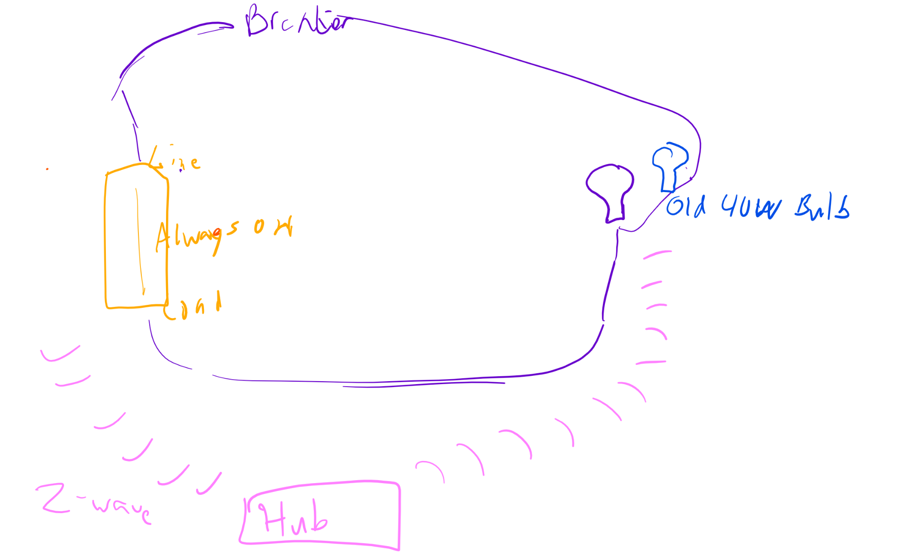
I can do non-neutral like this, disable local control. However, being a few smart bulbs, I have to add another older 40w light bulb in the path (or a bypass, which I’m trying to avoid).
Unusual, I’ve never tried the steal power from a smart device.
Thoughts:
I’m not sure how you can force the dimmer to say on 100%. You can set the min dim to 99% but I think the paddle will still turn it off.
If the force on problem is solvable, you could likely replace the old 40w bulb with a bypass. The bypass does the same thing and consumes little to no power.
You can’t hurt it in the configuration you suggest so I would say go ahead and give it a try.