The white with black tape is likely a live wire since that’s what you’re supposed to do if you use a white wire as a live wire. Not sure what you did but it doesn’t sound correct. You’re not really describing it clearly enough. Pictures could help.
Blue Switch has Line, load, red traveller, neutral and ground all hooked up.
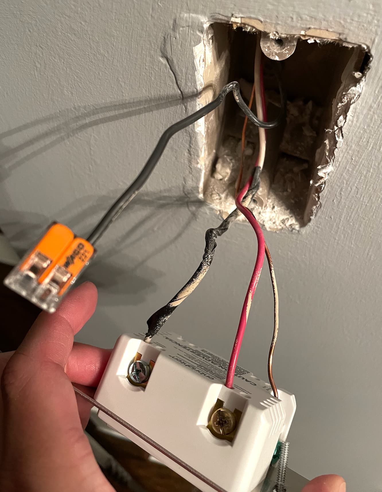
On the other end is a GE Aux switch with 2 terminals and a ground.
To the Aux switch I have hooked the red travelled on the top terminal. The white with black tape wire on the bottom terminal. And the bare ground on the top ground screw.
In the same Aux box is a black wire that I have capped off.
That is how everything is wired. No other wires are available.
It sure sounds like you are wiring based only on sheath-color assumptions… You said you have a multimeter - why are you not using that to verify each wire’s purpose?
Okay. Let’s start with getting a better description from you about what you have.
Are both of the switches in single gang boxes? In other words, an electrical box with one switch each?
Are your wires individual conductors or are they two or three conductors plus maybe a bare ground enclosed in an outer sheath?
It’s a little early to tell, but based on the little information you described, it sounds like in one of the boxes the white conductor has black electrical tape wrapped on it. More than likely, that suggests a non-neutral where power is first fed to the light.
Explain what you have in simple terms and post pictures if you can. The pictures should be with the switches pulled all the way out so that we can clearly see into the box and see all of the conductors easily. Also, don’t use terms like line and load. At this point they are just assumptions and you likely are not 100% correct about what you have
The Blue Series is in a 4 gang box with 4 other Blue Series switches. 2 single pole that work perfectly, and 1 3 way that also works perfectly. So I can guarantee that the Line in, Ground, Neutral and at least 1 of the travelers in the box is correct.
Attached is a picture of the single gang box that is on the other end of the not working 3 way setup.
Also attached is a diagram of all of the switches on the circuit. The green background items are working perfectly. The red background ones are the switches that aren’t
Okay, so you believe that this leg is being fed by a hot and neutral in the multi-gang switch box. So the key here is to understand the connections of the 3-wire in the multi-gang box as they were before you installed the Inovelli. Do you have pictures or a diagram of those connections?
There are two possibilities here. The three wire goes from the multi-gang box to the light box and then to the far switch or it goes from the multi-gang box to the other switch box and then to the light.
Unfortunately I don’t have a diagram of how the switches in the multi gang box were wired before I put the Inovelli in. I can say for certain that the line in and ground wires were all daisy chained between switches. The neutral was not used. The switches looked like this, with the load (black) and traveler (red) on either of the terminals. I cannot remember which.
I have a multimeter and am comfortable conducting whatever tests need to be done to figure out the wiring. My intention is to use these in smart bulb mode.
Thx. That makes it more difficult, but not impossible.
Is the switch leg you are wiring on the same breaker as the rest in the multi-gang box?
If the answer to that is yes, then we will start with your representation that power starts in the multi-gang box.
Based on the fact that power starts at the multi-gang box and because you have a single 3-wire in the far box, more than likely your wiring configuration is the light in between the switches. In this configuration, hot and neutral start at the multi-gang box. A 3-wire is routed to the light box and then another 3-wire is routed to the far switch.
Is this wiring a light or lights? Can you easily get at the light box, or “first” light box (where the 3-way from the multi-gang box would pass through)? Since we don’t know the original connections, it would be helpful if you can check the connections at the box.
It’s PROBABLY going to be this, although you can’t rely on your wire colors matching. In this configuration, the hot is passed over to the other switch box. At the light box, the hot from the first box is commonly attached to the white going to the far box, which in your case is likely why that white wire is wrapped in black tape (to signify that it is hot).
Is the switch leg you are wiring on the same breaker as the rest in the multi-gang box?
Yes. They’re all on the same breaker, which is actually acting up now so I can’t test the wires. But that is a different problem. Probably just an old breaker that needs to be replaced.
Is this wiring a light or lights? Can you easily get at the light box, or “first” light box (where the 3-way from the multi-gang box would pass through)? Since we don’t know the original connections, it would be helpful if you can check the connections at the box.
This is for 2 lights. Logically the power originates in the 4 gang box and ends in the single gang box just from the layout of where the lights are. I cannot easily access the 2 light boxes as they are over the 2 story stairs in my home. If we can’t figure anything out I can get to the back of them from the attic, but that is probably a last resort.
It’s PROBABLY going to be this, although you can’t rely on your wire colors matching. In this configuration, the hot is passed over to the other switch box. At the light box, the hot from the first box is commonly attached to the white going to the far box, which in your case is likely why that white wire is wrapped in black tape (to signify that it is hot).
Once I get the power back thru the breaker I am going to remove all wires from the aux switch and leave them loose while I turn the breaker on. Then I will use the multimeter to figure out if the black wire in the single gang box is actually the neutral. Does that sound like a good plan?
Um, not exactly. I don’t know how many, if any, of the 3-wire conductors are connected in the multi-gang box, so it’s hard to anticipate what you’ll find on the other side. But if I am correct in the wiring diagram I posted, you won’t have a neutral in the far box.
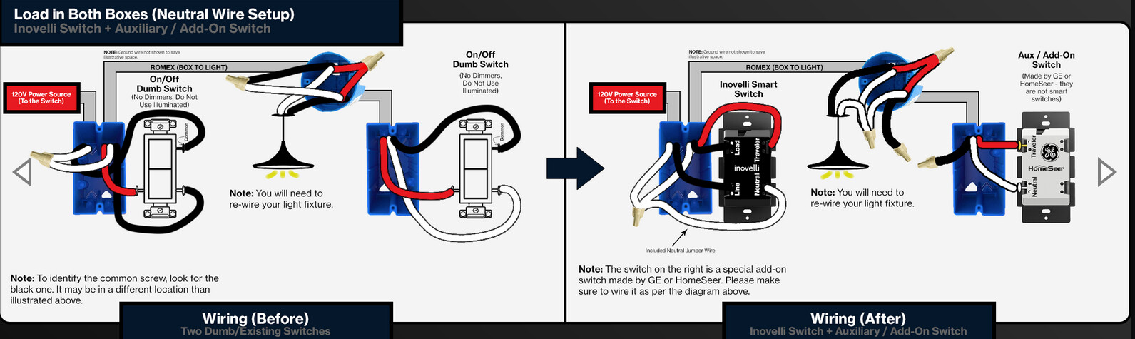
If you look at the dumb switch wiring wiring on the diagram I posted, you will see that the neutral gets sent from the panel side (multi-gang box in your case) to the light, where it is wired to the light (and goes no farther). (It doesn’t have to, as only the hot is switched.)
But in your case, you will need a neutral at the far box for the Aux. So to accomplish that you will need to re-wire at the light. That’s why it’s important to know what is going on in the light box. If I am correct and your wiring matches what I posted, you’ll need to get at that first light box to re-wire.
Well that is less than ideal, but if it must be done so be it. The only problem is both lights are can lights, so I probably need to get to the back side of them which means climbing in the attic. Not my favorite thing, but oh well.
Is there anything I can do for the moment to bypass the aux switch box? ie. Just make that whole box not do anything? I will leave the switch in there for aesthetics, but it doesn’t actually need to work. I just need the upper switch working for now, and I can rewire the lights later.
The best I can tell you is how adapt from the Inovelli drawing I posted, so it’s up to you to confirm what your actual wiring is. So I’ll tell you how to do it based on the drawing and you can adapt accordingly.
Start by removing all of the connections of the 3-wire in the multi-gang box.
In the multi gang box, connect a hot and neutral to the Line and Neutral terminals on the Inovelli. That will power the switch.
So now the only thing that is left is the Load. Drawing your attention to the drawing, you will note that the Load is actually fed to the light by the black conductor in the single gang box. So to get that Load back into the multi-gang box, in the single gang box you will wire nut that Load conductor and one of the conductors that is wire nutted together in the light box. Then the Load will have been sent back to the multi-gang box to be wired to the Inovelli.
So using the diagram as an example, in the single gang box, I would wire nut the black (which goes to the light) and the red (which is just passed through the light without connections) together. This gives me the Load in the multi-gang box which it connects to the Load terminal on the Inovelli.
Bear in mind that your colors/connections may vary. But if an electrician that follows normal practices wired this, it will look just like in the drawing. The fact that there is black electrical tape on the white conductor tells me at least some conventions were followed.