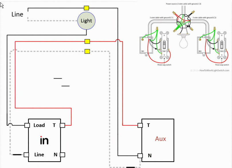
I am trying to wire up the vzw31-SN 2-1 dimmer in a configuration with a white series aux switch. The old 3 way setup had 3 leads in each switch box. Red, White, Black.
I’ve gotten the dimmer to successfully control the lights in either box with the black and white jumped together in the opposite box. I can’t seem to successfully determine what setup is needed to get the aux to be a part of this circuit and working properly.
I have changed the config settings on the dimmer in the Smarthings app.
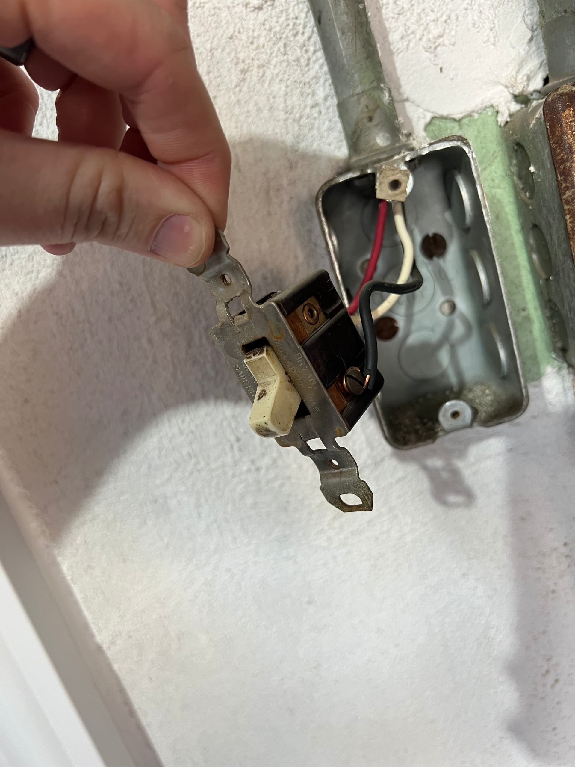
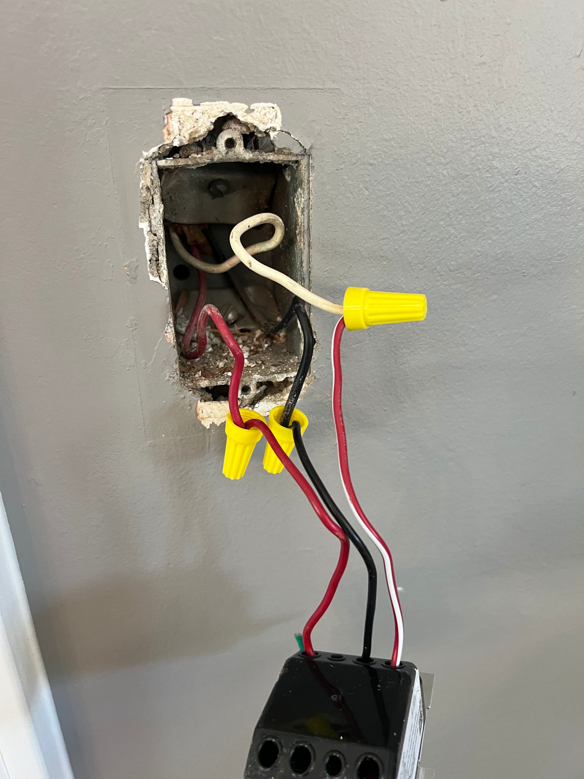
I have included 2 pictures of the original setup. Any advice?
If you have a single three-wire going to each switch box, then more than likely you have a power to the light wiring configuration. With the switches removed, you will find a single hot and one of the boxes if you test between each conductor and the ground.
So you have the hot without a neutral in one box and the load in the other box. So you will be wiring this as a non-neutral. If you want to wire this without rewiring at the light box, here is how it works:
The Aux switch goes in the box with the hot. Connect the hot to the neutral terminal of the Aux. Connect one of the remaining two wires to the traveler terminal of the Aux. Take the remaining wire and wire it to the second terminal of the Aux
If your wiring is as most electricians would do it, the two non-hot conductors you just connected our passed through the light box to the other side.
In the other box, you now have the hot and the traveler from the first box. Why are the hot to the Inovelli hot terminal and the traveler to the traveler terminal. The remaining conductor is the load going to the light and that goes into the load terminal.
The switch’s settings should be configured as a 3-way momentary to account for the use of the aux switch.
If you share details on that pigtailed switch and what the 3 wire colors mean then someone could likely be more specific in helping. I don’t recognize it and I’m not guessing.
In the first picture, the wire on the black common screw of the switch is either the load or the line power.
Apologies for not being specific. The pigtailed switch is a Lutron dimmer dvcl-153p. The picture with the normal looking non pigtailed switch is where I believe power is coming first. With both blacks disconnected the pigtailed black (black to the box) reads 12v. The other black to the box reads 32v.
The setup worked perfectly in the non smart setup.
Certainly getting frustrated here and about to revert to the non smart setup or just eliminate the three way in the garage and put the smart switch on the pigtailed spot. (Note that setup worked perfectly when I just twisted the wires in the garage together.)
So you will need to use a meter to find which conductor has 120 volts when measured between the conductor and the ground, which in your case is the box, hopefully. One of those six conductors has to be hot. The readings that you got less than 120 volts are probably induced voltage and are not what you’re looking for.
Wen you find that hot, then without rewiring at the light, the Aux goes there. Follow my instructions above for the rest.
You can puta the dimmer in either box, you just use the extra traveller to continue the load to the other box if the inovelli is in the line power box or you use the extra traveller to send the line to the other box if you want to put the inovelli in the load box.
Also just to reiterate what @Bry stated, your switch will be configured for a non-neutral switch. Depending on your load, you may need a bypass to ensure your switch doesn’t reboot unexpectedly or cause the bulb to flash while adjusting dim level. Just forewarning you in case you witness your switch flaking out. It’s most likely because of the non-neutral.