Saving the "best" wiring question for last

Hi all, once again i’m calling in the superstars (s’up @Bry) to solve one last wiring question. The last dimmer i have to put in is the most potentially complex. The existing switch controlled an outlet, and was also a part of a 2-gang with a dumb switch that controls an exterior light. It’s the outlet one i’d like to replace.

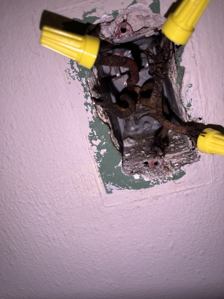
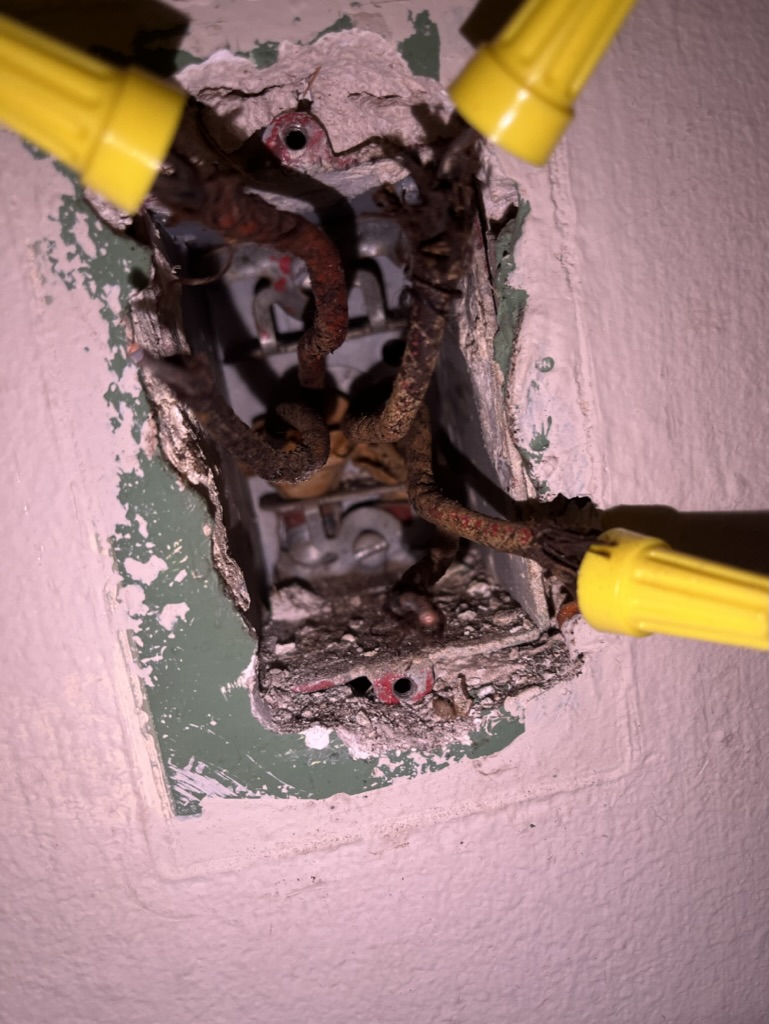
I’m not even sure where to start with this one so i thought i’d post pictures before i start tearing it apart and get advice on how to proceed and exactly what to test.

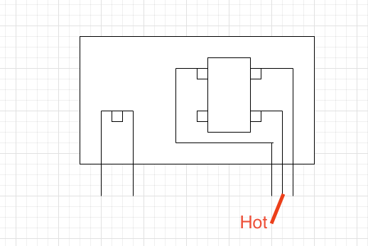
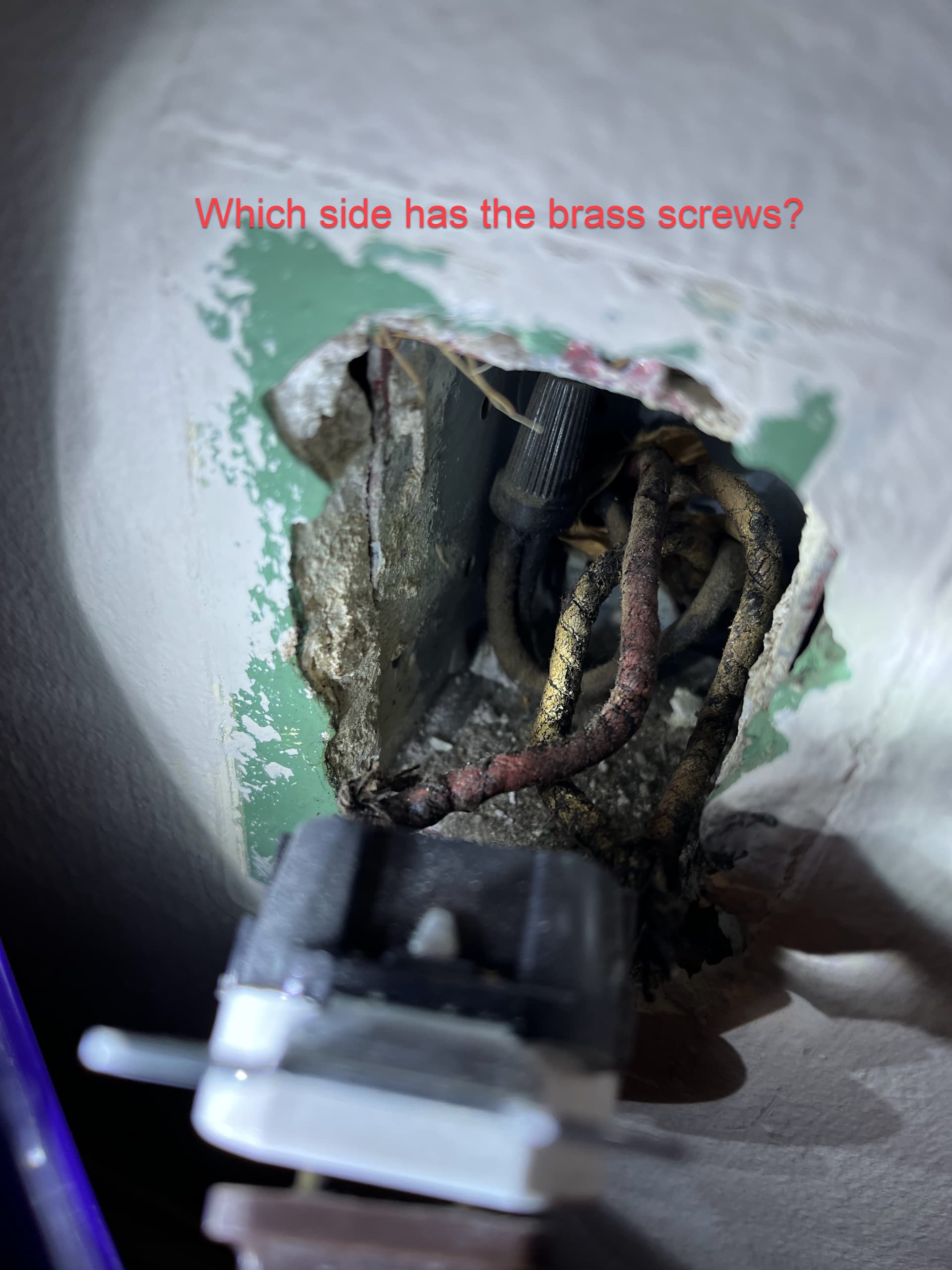
Here’s the outlet side:

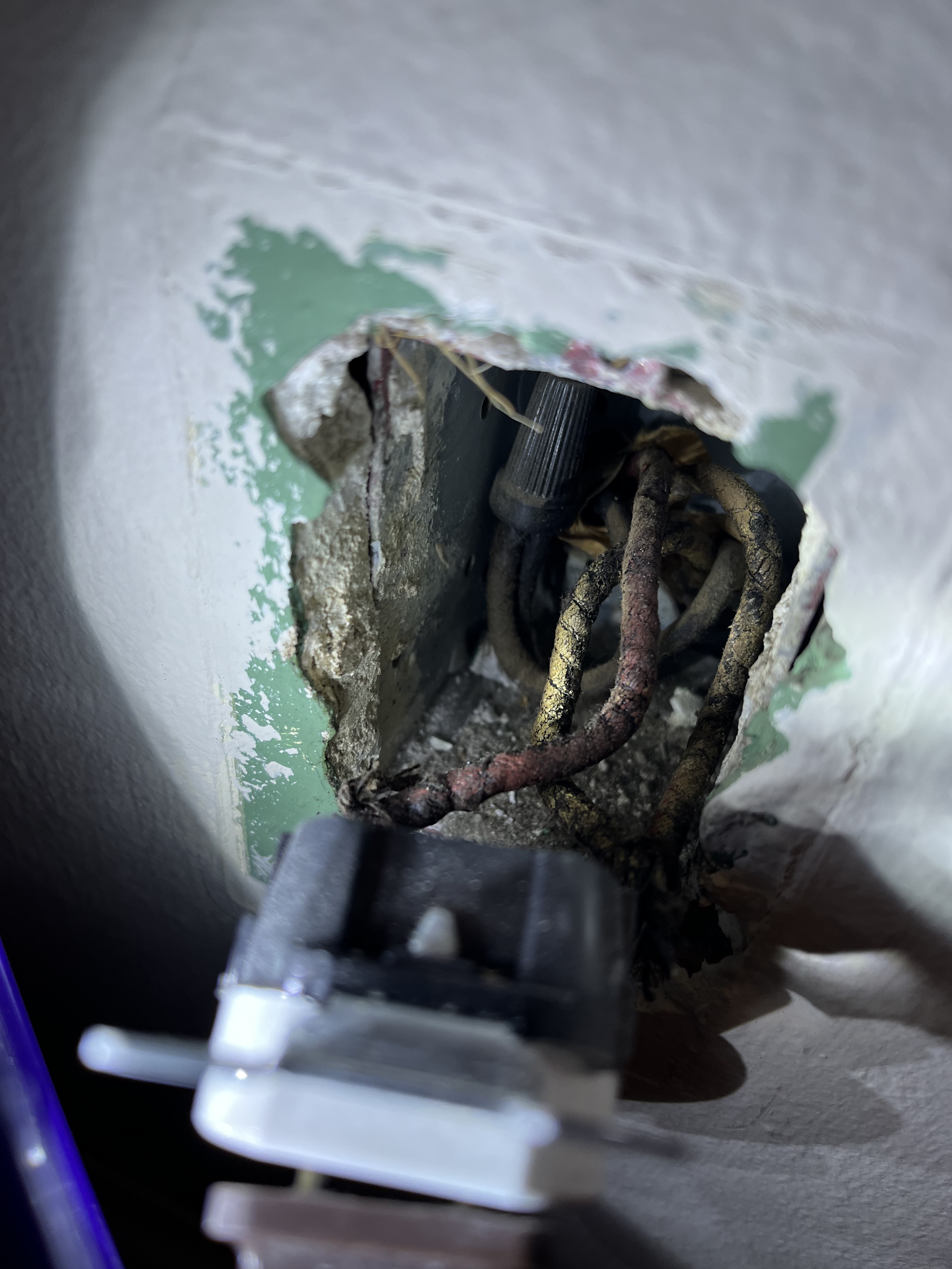
The outlet has four wires, all coming in from the bottom (nothing leaves the top). Two of the wires go to the “hot” terminals on the outlet, and one goes on the neutral side. the black wire on the left comes up out of the bottom of the outlet, gets tied in a wire nut, and then leaves back out the bottom without connecting to anything else.
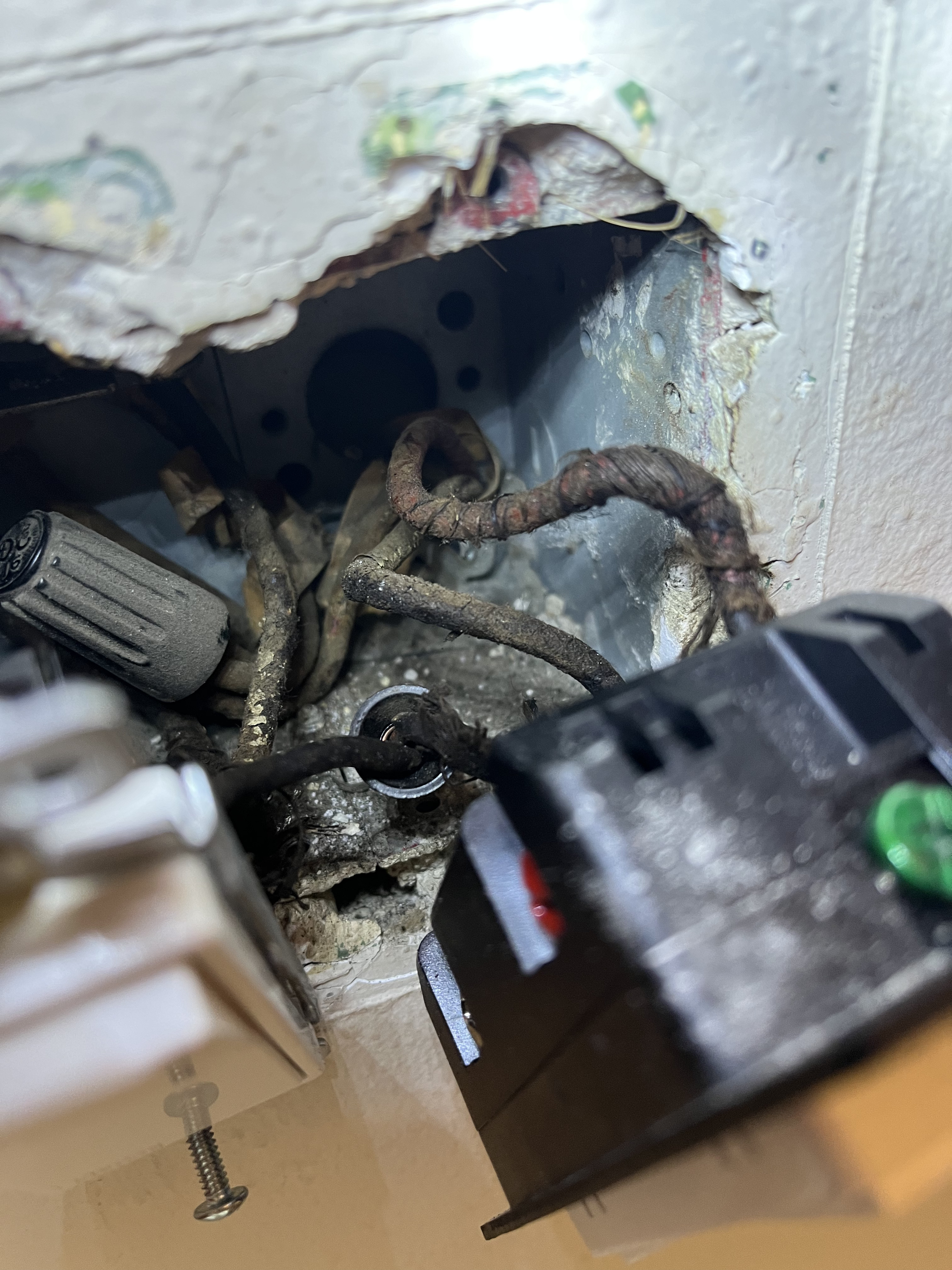
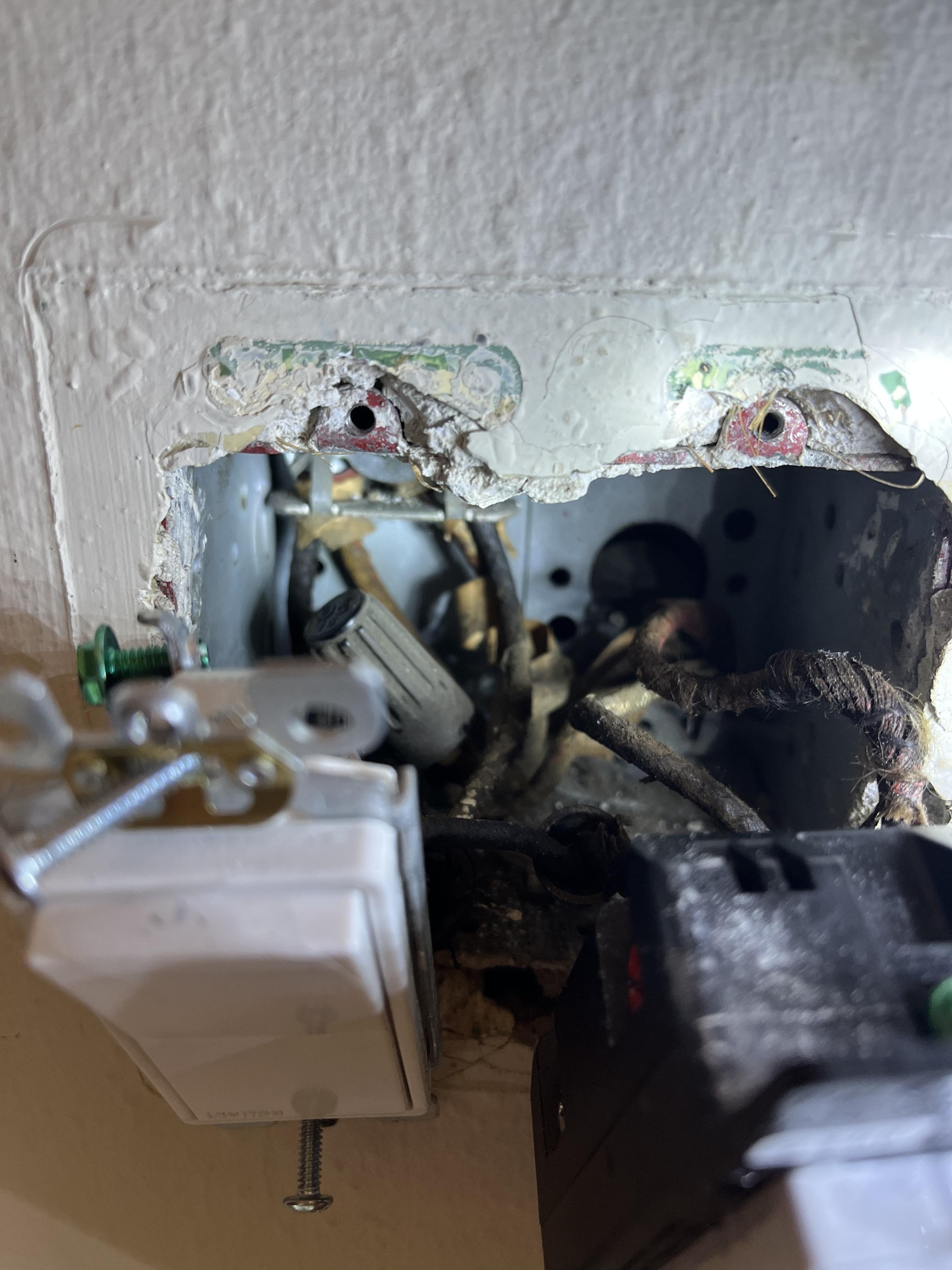
The switch side:


Apologies if the pics aren’t super helpful, i’m happy to provide any additional details.

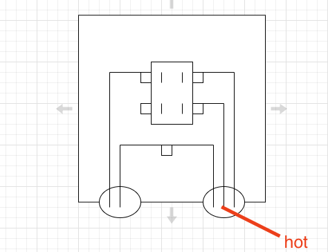
on the 2-gang switch side, three wires come up out of the bottom of the box to the dimmer switch. One goes into the hot side of the switch, then comes back out of the switch on the same terminal, goes over to the dumb switch’s hot side, loops around the terminal there and leaves the top (basically a “load side daisy chain”).

A second wire starts at the dumb switch’s second “hot” terminal and exits the top of the box.

Another wire (i’m assuming the red you can see in both places) comes out of the bottom and goes to the “load” side of the dimmer switch.

The last wire that comes out of the bottom goes into the wire nut, which ties it to two wires that leave out the top, presumably to the exterior light. Nothing is attached to the neutral side of either switch.

So totalling that all up:

Outlet: 4 wires come out the bottom, none out the top (including one that basically just comes into the box and does a u-turn)

Switch: 3 come into the box, four leave the top

All that being said, apologies for the lack of information at the outset, but A) i was almost afraid to mess with what was currently there, as it’s the most confusing setup to date, and B) we’re in the middle of a thuderstorm, which would make disassembly without natural light in the room difficult.

Given what we know so far, i’ve got two questions - 1) how would i replace the dimmer to control the outlet, much like i have for previous ones on this floor, and 2) is there a way to make this wiring setup cleaner? I feel like there’s a lot of extra loops and such that don’t need to be there, but that may just be my OCD kicking in.

What are the next steps to look at/disassemble/investigate?

Thanks all for you your help, as always!

One thing worth noting is that I’m pretty sure the outlet in question represents the end of the “chain” That starts with my sons bedroom (from my first wiring help post).

Just as an fyi you are running risk using these switches to control an outlet. If the load goes over the rated amount, it can result in a fire. These switches are really meant to only handle lights, not outlets.

Yep, I’m aware. bry has been walking me through wiring things up in such a way that the switch has no load, it’s just getting powered from the wiring and then acting in smart bulb mode. They’re not actually controlling any load directly.

1 Like

So let’s start with the receptacle. I do not believe that it is the end of the run. If it was, you would have a single two wire to it. And the two conductors of that two wire would be directly connected to the receptacle. Instead I see more conductors and at least one wire nut.

So take another look in the receptacle box, please. Tell me what you have coming into it in terms of two-wire, three-wire. Don’t just say four wires as it doesn’t tell me much. It is a little tough to see into the box, but I am guessing there is a three-wire and a two-wire. The reason that I am guessing there is at least one three wire coming into that box is because I see a red conductor.

I will wait until you report back, but I believe that this receptacle is in the middle of the run. The red conductor of the three-wire is likely the switched conductor. The black of the three-wire will be constantly hot so that it can send that downstream.

Hi Bry, i did some more checking this morning when i had adequate light to work with the breaker off. My findings pretty much fall in line with what you said. Here’s a quick diagram:

image

It’a three-wire coming to the receptacle. The line going to the bottom of the two “hot terminals” on the receptacle is the only one that’s hot when the receptacle is removed.

There’s also a completely separate line that i’ve illustrated on the left that comes into the box, goes into a wire nut, and then leaves the box the way it came. That line appears to be cold when the breaker is on - not sure what it is or where it’s from/going. That’s the wire nut you see on the left of the receptacle photo.

I’m going to go do some resistance tests to figure out what in the receptacle box corresponds to what in the switch box, but i wanted to get this to you ASAP.

That would be incredibly odd for both wires in a “line” to be connected to each other, unless it’s capped off at the other end as well. But when capping off I’d expect a nut on each wire not bundled together like that.

It looks completely irrelevant to what you’re trying to do, but I’d still have questions about it lol

Yep that’s kindof where I’ve mentally “filed it”. Not only are they unrelated and capped off, no switch or breaker seems to make them hot. Wouldn’t be shocked at all if it was just some old wiring that got capped off.

Ok, just to confirm. For the 2-wire, the black and white conductors (FOR THE SAME 2-wire) are wire nutted together?

Also, is this a split receptacle? It doesn’t make sense to have 2 of 3 conductors from the same 3-wire connected to a receptacle if it’s not.

When you checked for voltage, 3-wire black to white and 3-wire red to white, did you test with the switch in BOTH positions? I’m guessing one pair will be hot constantly and the hot intermittently based on the switch position.

I’m away from the house at the moment but I N can respond to some of these, and then do a more thorough test when I return:

For the 2 wire, it’s actually two black wires nutted together.

The receptacle isn’t split (afaik none of the ones in my house are but I checked this one to be sure).

I’ll do more thorough voltage testing when I return, but as for the colors (assuming they haven’t changed or rubbed off with age), the wires attached to the lower line terminal AND the neutral were both red. The one attached to the upper line terminal was white. The lower line terminal (red) was hot without the outlet installed, the white was not.

With the outlet removed from the box, the dumb switch that controls the exterior light functions the same as if it were there, and the dimmer doesn’t get power at all. But the dimmer could also be installed incorrectly so I wouldn’t necessarily rely on that.

The “hot-ness” of the one wire in the receptacle box doesn’t change regardless of the position of the working switch.

I’ll do a more thorough multimeter test when I return in an hour or two!

Please pull that receptacle out. The wire nutted connection two. GOOD pics into the box, pls.

Hopefully these are up to snuff:


The two wires with nuts on the right were going to the two terminals on the “hot” side of the outlet. The one with the wire nut on the left was going to the “neutral” side. the two non-capped wires were the two that were originally tied together.

After untangling a bit, it looks like they’re entering the box as two separate “bundles” - the two on the left and the three on the right.

Ok, so you have a bundle of two on the left and three on the right. Previously, you thought that the two wires wire nutted together were from the same bundle. But it looks to me like the two wire nutted together is one from the left and one from the right. ??? If that is the case, then your previous drawing is not accurate. If so, can you redraw it.

Is there more than one receptacle that is switched by the switch?

That’s correct. Here’s an updated drawing that illustrates how it’s actually going. Apologies for the error:

image

This is the only outlet that’s controlled by this switch.

In this picture of the receptacle, which side, right or left, has the brass screws? After looking at this more, this could be a standard switched receptacle with 3-wire, except the switched hot is on the left side. The brass should be on the right, however. So either the receptacle is upside down or it’s wired incorrectly in reverse.

I see one red on the left and two conductors on the right, without testing, that looks like the switched hot on the left and probably the neutral conductors on the right. There would be two only to send the neutrals downstream. I also see what looks like two blacks bundled together, which would also be consistent with a constant hot being sent downstream.

The problem is what I’m thinking should be the neutrals you are saying are hot. How confident are you in your measurements?

Pretty confident. (or i was until you said that lol). Easy enough to know which one is the hot one when there’s only one in the whole box that is :slight_smile:

That being said, the brass are on the right, silver on the left. That i am very confident about.

Given the fact that all of the outlets and switches were replaced right before we bought the house, and i’m fairly certain they were replaced by the previous owner, it wouldn’t surprise me at all if the wiring was done incorrectly. It wouldn’t be the first time i’d found one that was wired wrong - To the point where multiple times we’ve debated calling an electrician out to basically pull out every switch and outlet in the entire house to verify they were installed correctly.

Honestly if it comes down to that…you may want a quote to update all house wiring.

Yeah, the number on the quote is basically why we haven’t done it yet :slight_smile:

Half of the house got updated with a basement renovation last year, but to do the upstairs as not part of a full reno would be expensive/destructive, so we’ve passed on it for now.

Running out of options, but let’s try this:

Put the original dumb switch back in as it was before. Hopefully you took pictures so you can re-create it.

Leave the switch in one position and then using your non-contact tester, test each of the five wires in the receptacle box and let me know which is hot.

Then put the switch in the other position and do the same thing. So two series of tests.

By chance, is there more than one switch controlling this receptacle?

Yeah, i may be reaching the limit on how much time i’m willing to spend on it, to be completely honest. I’ll do what you recommend, but in the meantime i think i’m also going to reach out to a local electrician to take a look…i think my wife is reaching her limit of how many times i turn half the top floor of our house’s power off :smiley:

Thanks again for all your help!