At this point it’s experimentation. But at least taking the switch out of the equation.
I’m not quite sure what to make of the white connected to the common terminal. But for now I guess you have to presume that the white is connected to the line side of the light. Seems strange too use that conductor but it doesn’t necessarily make it incorrect.
I just hope it isn’t wired in correctly to start with and your switching the neutral.
Do you have a meter or a non-contact voltage tester? I’d like to trace if you do.
Okay, in the switch box, connect the red from the 3-wire to the load terminal. Turn the switch on and use the non-contact tester in the upstairs box to see which of the three conductors on the 3-wire is hot.
Make sure that the switch he said as a two-way or just factory reset it. I’d also use the non-contact tester to see if the red in the switch box is hot after you turn the switch on.
Also let me know if the switch LED bar displays the standard blue or if you’re getting the funky colors again.
I connected the red wire in the downstairs box to the VZM32 LOAD terminal.
I used the non-contact tester to confirm that the RED wire on the upstairs 3-way dumb switch has voltage. None of the other 2 wires on the upstairs 3-way dumb switch have voltage.
The VZM32 LED is on blue and looks okay.
The upstairs 3-way switch is in a position such that the red wire is isolated (it’s not connected to the load). If I flip the upstairs 3-way switch such that the red terminal is connected to the load then the VZM32 LED flashes yellow and cyan and the incandescent bulb flashes every few seconds.
I didn’t leave the 3-way switch in this position for long. I switched it back and now the VZM32 has the blue LED on.
Thank you for your patience with me to figure this out.
Okay. Remove the 3-way switch from the upstairs box. Connect the red and the white together and test. Because it was connected to the common screw, the white should be feeding the hot back to the light, hopefully.
Yeah, I am too. We’re essentially replicating what you were getting at with the switch thrown on one position. But I wanted to take the switch out of the equation just to make sure.
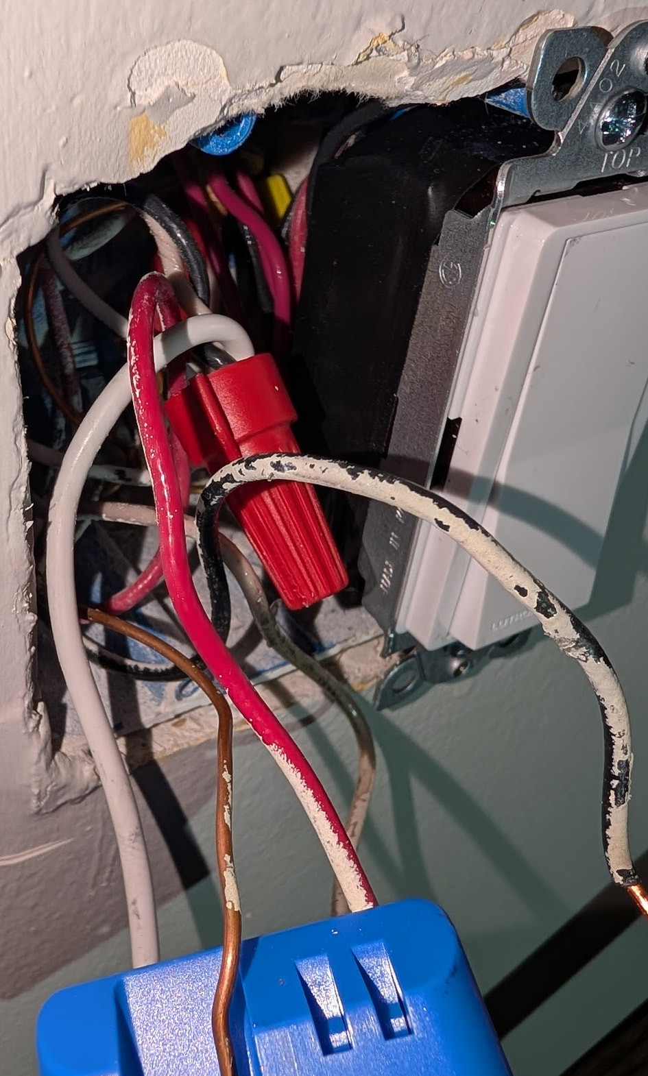
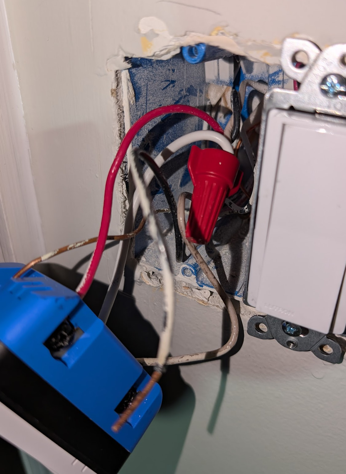
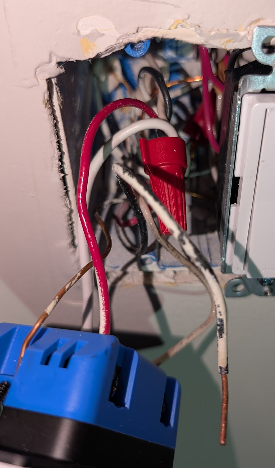
If you get the flashing LED, just for the heck of it post a picture or two of the box with the Inovelli so I can see inside the box.
The neutral bundle includes the black wire from the 2-wire (left) romex and the white right from the 3-wire (right) romex. The 2-wire (left) romex is the line romex from the panel and the 3-wire (right) romex feeds the 3-way switch. The neutral bundle also includes the white pigtail for the Inovelli neutral.
It’s odd to me that the 2-wire Romex white wire is the LINE. Normally the LINE should be black.
Is there a scenario where they would have the hot go to the wire nut bundle? If so, why do I see 120v on the white wire which I claim is the LINE? I don’t see 120v on the neutral bundle when measured to ground which makes me think I’m correct in calling it the neutral bundle.
I couldn’t get the camera to focus on the back of the box to make it easier to see. Hopefully the description above helps.
Ok, so what you’re calling the left Romex is the 2-wire, right. You previously said this is the line in from the panel.
On that 2-wire (stop with the left and the right, pls), the white is hot? That makes sense for a non-neutral with power to the light. But your mention of the black from the 2-wire being connected to the white bundle doesn’t make any sense to me. I thought you had the switch powered up with both connectors from the 2-wire, so how can one of them be connected to the white bundle???
You said the black from the 3-wire is disconnected. Check.
You said the black from the 2-wire is connected to the white bundle. Ok.
But there is a black connected to the switch. So where is that coming from? There is only one black each in the 2-wire and the 3-wire, which equals 2 blacks. But you’ve described 3.
Yes, left is 2-wire and right is 3-wire. Sorry for confusing that.
Yes, 2-wire the white is hot.
Yes, I can power the switch by using the white HOT/LINE from the 2-wire and the white pigtail to the neutral bundle. That correctly powers the switch. That’s using both wires from the 2-wire: white (hot) direct to the switch and black via the neutral bundle.
The 2-wire black (which I think is a neutral) connects to the neutral bundle.
The 3-wire black is currently not connected.
You said “But there is a black connected to the switch”. There is not a black connected to the VZM32.
The VZM32 has LINE (2-wire white), NEUTRAL (white pigtail to neutral bundle), LOAD (3-wire red)
There are only 2 black in a 2-wire and 3-wire collectively. But you’ve described 3 . . . one attached to the white bundle, the loose black from the 3-wire and the one attached to the switch. Where is the third black coming from?
You said “But there is a black connected to the switch”. There is not a black connected to the VZM32. I don’t see where I said that, but if I did I was wrong. Sorry.
The VZM32 has LINE (2-wire white), NEUTRAL (white pigtail to neutral bundle), LOAD (3-wire red)
I’m feeling like this is a non-neutral with power to the light first. Not what we’ve been thinking. If the black on the 2-wire was hot, that would typically be a panel feed. But a white on the 2-wire being hot usually means power to the light.
Sorry. Got confused. The black I attached was from the 3-wire. So sorry.
For the 2-wire black: it’s currently part of the neutral bundle, can I use the white pigtail from the neutral bundle or do I need to separate just the 2-wire black wire?