Hi, So I am one of those DIY enthusiast who is learning “on the job”. I have a wiring/installation question/dilemma that I want to run by this awesome community. Note, I have installed a couple of TP link dimmers and couple GE Z-wave on-off switches.
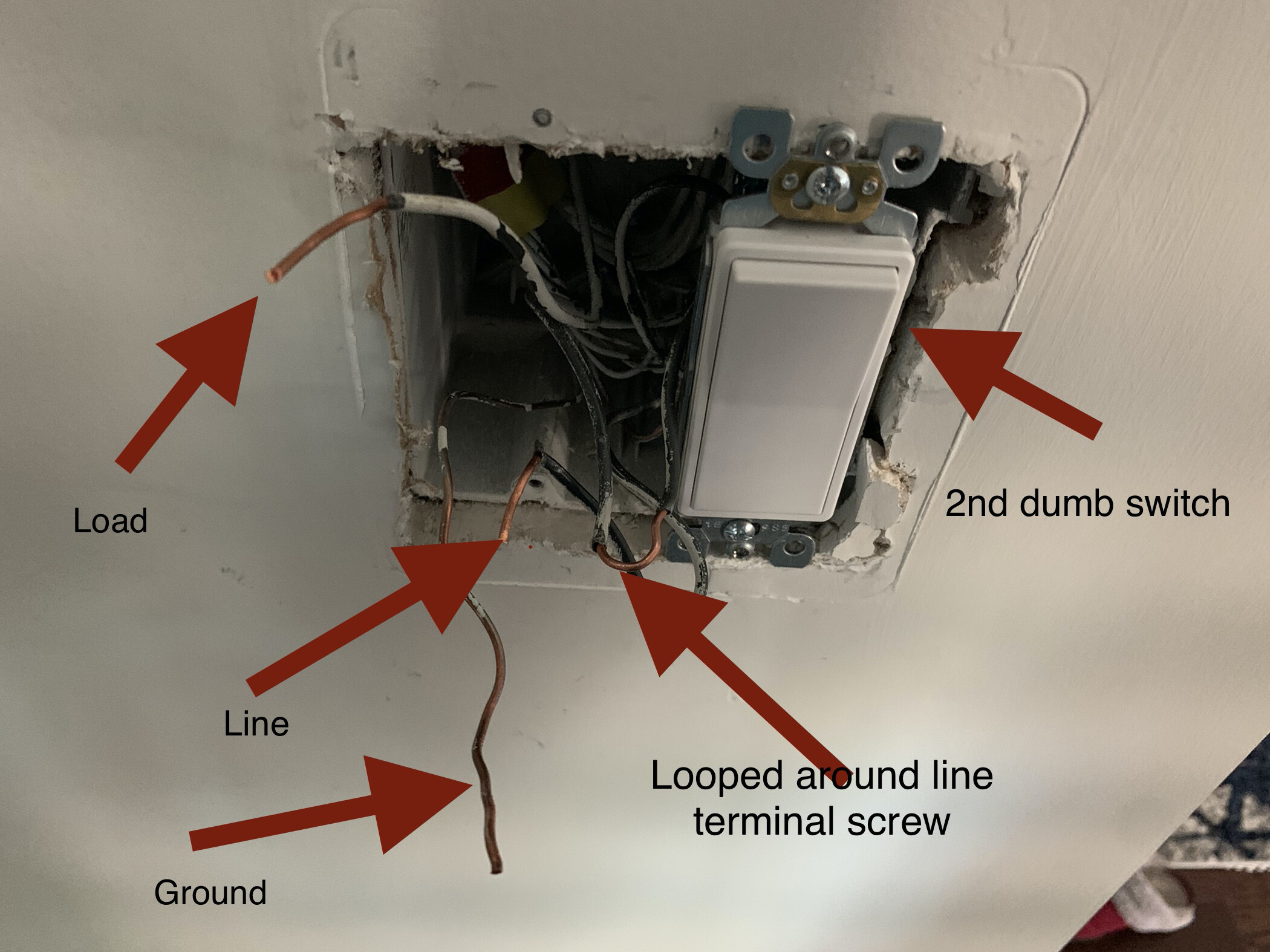
So, coming to the problem, I am trying to install black series dimmer in a 2-gang box. One switch is powering the ceiling lights and other one is powering wall outlet. I am replacing the switch that powers ceiling lights obviously. Now, what I am seeing is that there apart from line/load/ground/neutral wires, there is one more wire that is “shared” by both switches. It was looped around the screw on my existing dumb switch. I tried to install black series trying to do the same, that is loop that wire around screw on dimmer switch. However, it appears that the screw on dimmer doesn’t hold this well and the either the load wire or the looped wire comes out when I try to tighten the screw. I am not sure how to get around this situation. I had similar setup for one of GE z-waves I installed which was also in a 2 gang box and I was able to easily loop the other wire around screw on that switch.
So, I am wondering how to proceed with this installation? Should I cut the loop wire and use a small wire, one end of which goes into dimmer and other is connected to the cut looped wire via connector nut?
Here is the picture. I am sure this helps visualize the issue more than words above.
Seems like you need to ensure the screw is backed out (not removed) and ensure the blade of the connector is expanded; then insert both line wires through the 2 holes for Line on the Inovelli. Or you can make a pigtail, twist/wire nut all three copper ends together and connect the other side of the pigtail to the Inovelli switch.
Actually, for that middle-stripped conductor, you can just turn it around by looping it over the dumb switch first and then backstabbing the end into the Inovelli. But any of the above will work.
The bigger question is do you fully understand your wiring? I would expect that middle-stripped wire to be the line. But you think the other conductor is the line. Unless I’m missing something, you have an extra black conductor for a 2-way switch.
Thanks @harjms and @Bry for your response. The only reason I think the middle strip wire is line is because it was hooked into the line terminal of dumb switch and the looped wire was also wrapped around screw of same terminal. I will try to loop the wire around dumb switch and back stab other end as you suggested and report back.
I agree with you that the middle-stripped wire is probably the line (although you should test between it and the neutral bundle (can’t see into your box) to confirm.
But I think you’re missing my point. If the line is the middle stripped wire, what is that OTHER conductor that you have labeled as the line?
Actually, I haven’t labeled the other conductor as line. It says “looped around line terminal screw”. Having said that, honestly, I have no idea what that other conductor is for. All I know is that it is there and lights and outlet controlled by switches from this box are not controlled by any other switches anywhere else in the house so that makes me believe that both switches are 2-way and not 3-way. I also have another box on the other side of the wall. This box too has two switches and one of the two switches is a 3-way switch. I don’t know if that helps. And honestly, I don’t know if this box should have anything to do with what the other box has. I just mentioned because they are sharing same wall.
Regarding neutral wires, they are there bundled inside the box. I just didn’t had that pulled out when I took the picture.
Do you have pictures before you removed the conductors from the dumb switch? That will make it easier to diagnose. That extra conductor may be the line going out of the box downstream. But you will have to determine if that is the case and figure out which of the two is that conductor and which is the load.
It sounds like you have it right. A single pole switch only has 2 screws and 2 backstab spots so if those wires were together at the one end then they are all line power. That looped wire will go over to the other switch and end there, so reverse it and get a neutral pigtail and then you should be good to go.
Sorry for being AWOL. Thanks @PJF@Bry for your suggestions. I was able to successfully install switch by following your suggestions by reversing the connection with looped wire going into dumb switch and 2 backstabs going into the line terminal of black series. Everything is working as expected. Thanks for your help.