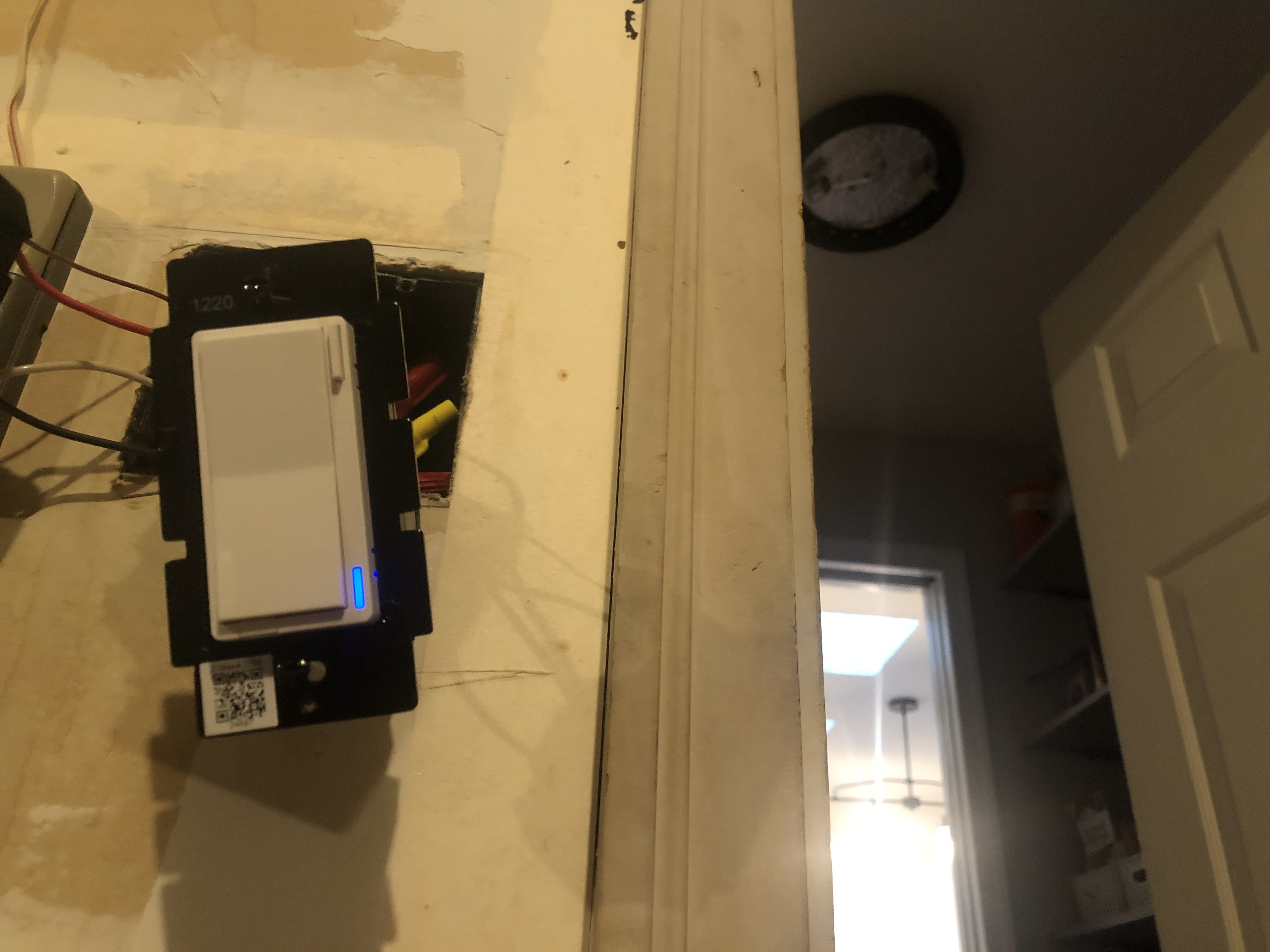
I have a Red On/Off switch in a 3-way configuration with a dumb 3-way switch powering a single light. It is showing extremely odd behavior but I think I’ve narrowed it way down.
The Inovelli switch will not send power out of the red traveler terminal to the dumb 3-way switch.
If the dumb switch is in the position such that it expects power coming in over the wire connected to the Inovelli Load terminal and then I turn on the light at the Inovelli switch the light will come on.
If I test Load to Ground I see 110Volts as expected.
If I then turn the Inovelli off the light turns off, I no longer see voltage at the Load terminal, but I also don’t see voltage between the Traveler and Ground. This leaves the dumb switch “dead” if you will. There’s no voltage going to it.
I could outline a few other scenarios but I’ll stop for the moment. Just like a normal dumb switch, shouldn’t either the Load or Traveler show voltage at any point in time? Otherwise, how does the dumb side work?
Okay, so I’ve done a lot to troubleshoot this. Here goes (in no particular order):
I’ve replaced the switch with a new one.
I replaced that new switch with an even more newer one
I have a few lying around
3 switches all exhibit the same behaviors
Removed the inovelli switch and replaced it with a dumb switch
the two dumb 3-ways acted like they should
proves (maybe?) that the wiring is set up correctly.
Removed the nodes from my zwave network and re-added
back when I thought remote control was part of the problem
in my most recent troubleshooting I don’t even bother pairing the switches
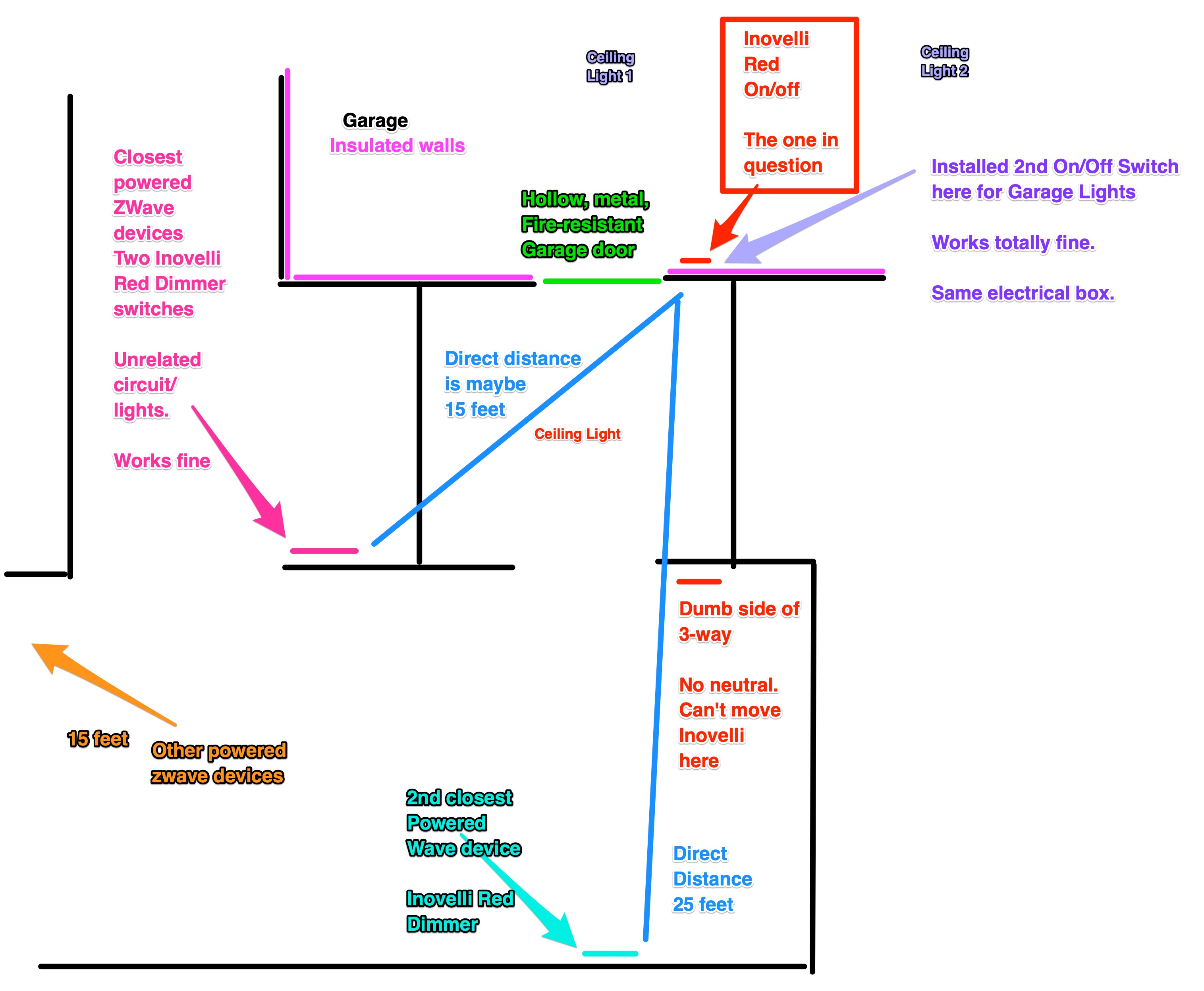
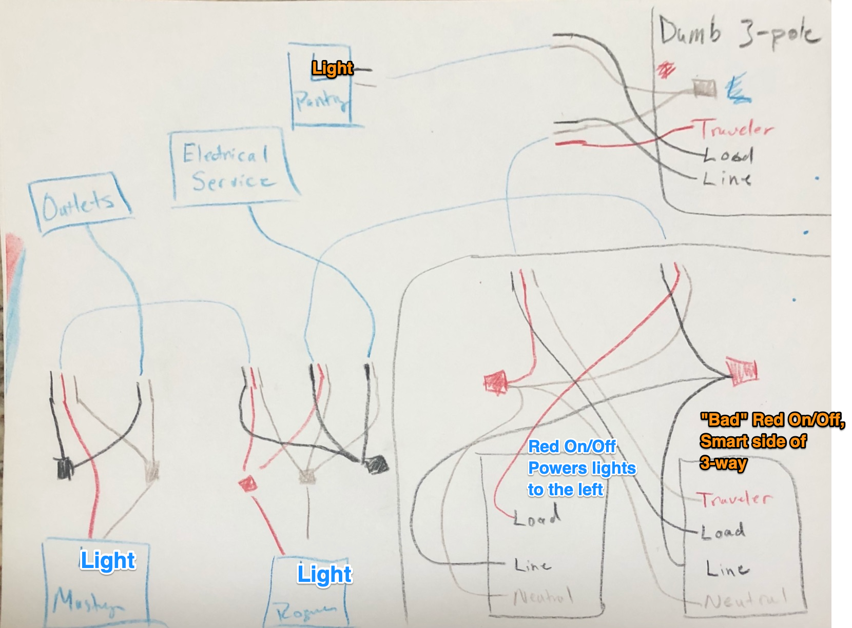
Open all the electrical boxes on the circuit and draw a diagram of the wiring (see below)
I thought, hey maybe there’s some weird wiring happening here.
it seems pretty normal to me - nothing too crazy?
Removed all 23 devices from my zwave network, reset the controller and repaired everything
this was possibly overkill and very much not fun
“healed” the zwave network
again, when I thought zwave had something to do with this
signal test (hold config for 5-10 seconds then release)
they all pass
results were solid green, or solid green then red
which I believe means the device isn’t paired)
Drew a whole diagram of this corner of the house
again, when I thought the issue was zwave network related
Made a quick video
Shocked myself zero times.
that’s a win, right?
Speculation time:
Is it possible the switch detecting a short on the traveler and killing the power to it? If that’s the case how come the circuit works with 2 dumb switches?
that looks strangely familiar to a problem I’m having with a Red Dimmer in a 5-way
Like you, I have done a lot of troubleshooting, including swapping switches and doing full resets. But still unable to figure it out. But in my case, it works fine as a 3-way or 4-way. Its only the 5-way that starts acting weird.
My suspicion is that the length of wire, as well as running parallel and through several other boxes crammed with live wires, is causing some kind of induced phantom voltage that is messing with the sensing logic in the Inovelli. But that is just a wild guess as my AC voltmeter is not reporting any phantom voltage, but my non-contact AC detector does beep which indicates some inductance is present.
@Bry the wiring diagram I drew is color-coded So, I believe there’s a black wire running to the common screw. It’s the black wire paired with the white that runs off to the light. The other black is the traveler in the 3-wire romex. I can triple check that tonight, but I believe it’s correct.
The light fixture has two 60watt led lightbulbs - is that what you’re looking for?
@mamber interesting. Yea, I was thinking my next step was going to run some romex between the boxes through the room, bypassing the wires in the wall. I kinda hope it’s not that though, because then I’d have to poke holes and paint things I’ll post back here with what I find.
Don’t take this the wrong way, but I stared at that drawing a while and it made my head hurt, lol.
That sounds correct on the dumb switch. The black common screw should contain the black of the 2-wire going to the light(s).
Let’s take this one step at a time. The easiest is to exclude LED bulbs as the culprit. Can you temporarily swap out for incandescent? LED bulbs have occasionally been at fault.
There is something causing the relay to flip back to the on position in the early part of your video. Not sure why though. But there are a number of steps to try so we can go through them one at a time.
Don’t take this the wrong way, but I stared at that drawing a while and it made my head hurt, lol.
I’m not offended it was the fastest solution I had - the kids’ colored pencils. If there’s a better/free tool please tell me!
Let’s take this one step at a time. The easiest is to exclude LED bulbs as the culprit. Can you temporarily swap out for incandescent? LED bulbs have occasionally been at fault.
I’ll try that. For whatever it’s worth, I have the exact same fixture using led bulbs on a different 4-way circuit. Works a-ok. Not only that, but this all all started before I swapped the current fixture into place. It was originally an older 4-foot long, 2-tube fluorescent fixture.
But there are a number of steps to try so we can go through them one at a time.
Is there any reason to test the voltage drop at the load and traveler terminals with no bulbs at all? Asked another way: does the switch cut power to a terminal if it doesn’t detect a load?
Same for me. I understand LEDs can cause weird behavior with smart switches. But I have the same Lights throughout the house and they work fine. Even still I tested with an incandescent and it made no difference for me.
They definitely attempt to sense which terminal has the load. That is how they can work with ‘dumb’ 3-way switches. This makes it hard to test with just a voltmeter. What I was seeing was voltage on both the Load and Traveler terminals. However that does not mean it was running current through both terminals. I believe the sensing circuit needs to present voltage to both terminals so it can detect which one draws enough current to decide ‘this one has the load connected’
After you test with incandescent, double-check to see if you set parameter 13 to 1 in the past. That’s for T8 loads which you probably would have used with a fluorescent. If you are using a standard fixture now, it should be set to 0. I know you tried several switches, so this likely isn’t it, but it’s worth checking.
Even if the incandescents don’t resolve the problem, leave them in for the time being.
Next up, I read the fine print on the LED bulb I was previously using. It’s was a NON-dimmable LED bulb. So I thought, okay, maybe I should try with a dimmable LED bulb. Maybe non-dimmable bulbs are no good. (not saying this is sound logic, but go with me for a minute here).
I swap in the dimmable LED and get similar results to that video. Generally, the switch can end up in this state where the switch’s LED is on, but the light is off:
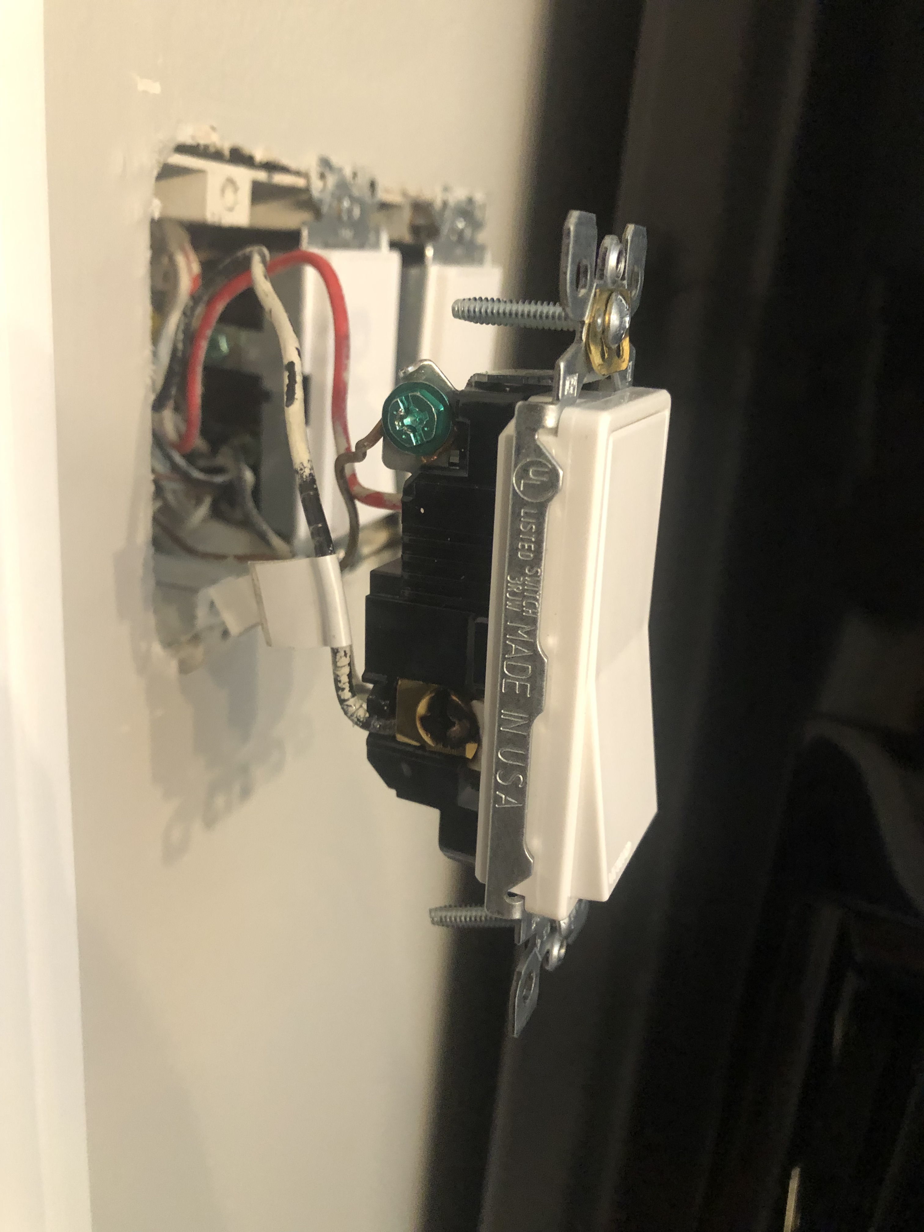
Ok, so I think: If the LED is on, is power flowing to the dumb switch? Let me test the dumb switch. I grab my tester and test one of the travelers (the black one) to the casing on the switch (e.g. ground) like I’ve done a thousand times. Unless there’s a fault it should be safe to test anything to ground, right?
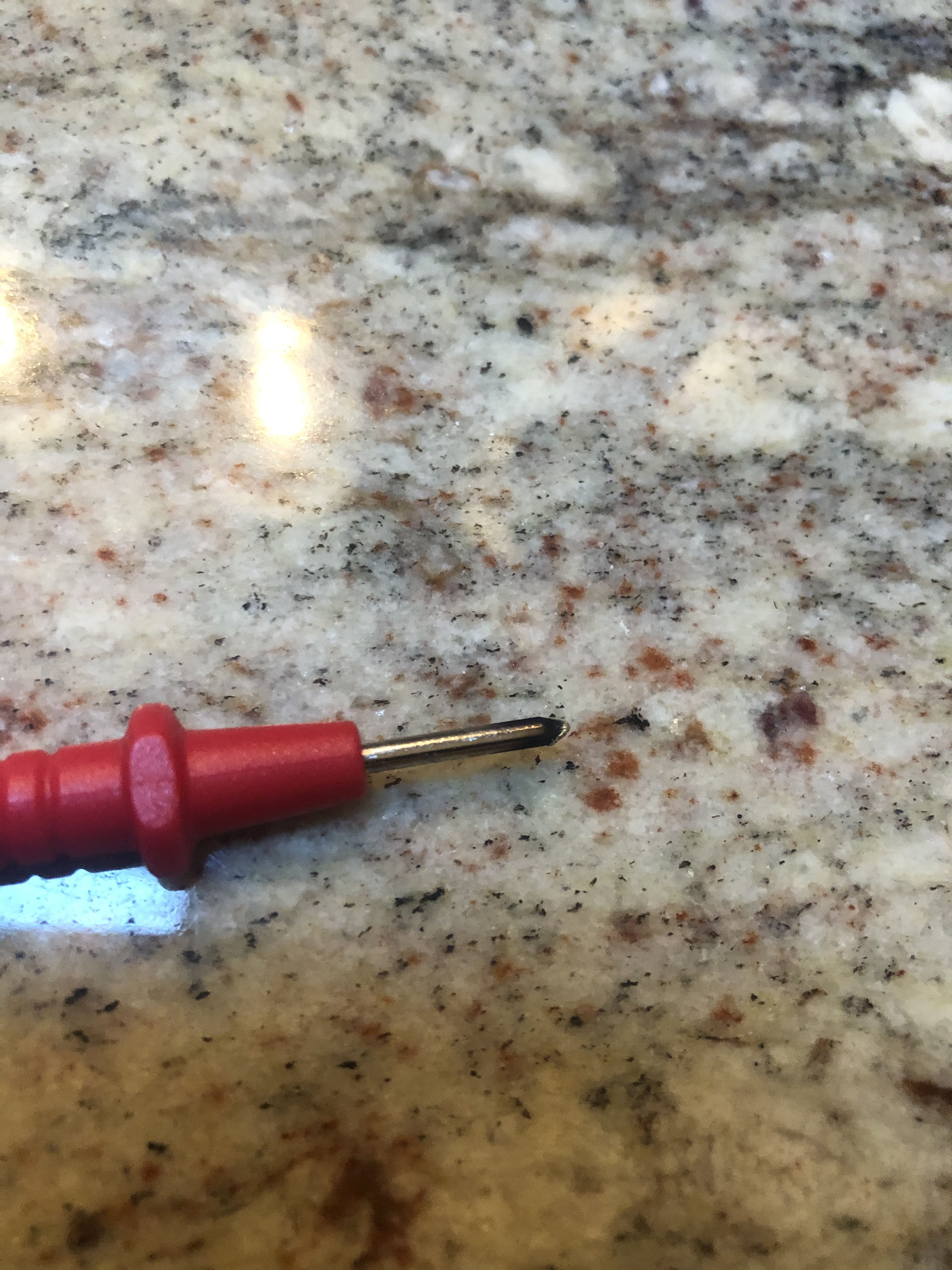
Nope. Sparks fly, circuit pops, tester turns all carbony. Carbon on the traveler terminal.
Well, that’s interesting. Presuming the meter was set to test AC voltage, I don’t understand what might have occurred. I’ve never done that testing with a smart switch installed, so I’m just not sure.
As a next step I would replace the dumb switch, in part because of the quick flash, plus it’s an inexpensive thing. Let’s leave the incandescent bulbs in for testing for now.
If that doesn’t get it, the next step is to wire it as a 2-way. Post back after you swap the dumb switch.
Yes definitely check which side of the meter you have the red probe in. Likely had it on current testing (up to 10A) side instead of voltage testing side.
@jaaasshh I see it was mentioned, but just want to make sure you have tried toggling parameter 13 between 0 & 1 (testing both options). Might want to pull the air gap and pushing it back in after changing the parameter.
 So, I believe there’s a black wire running to the common screw. It’s the black wire paired with the white that runs off to the light. The other black is the traveler in the 3-wire romex. I can triple check that tonight, but I believe it’s correct.
 I’ll post back here with what I find.