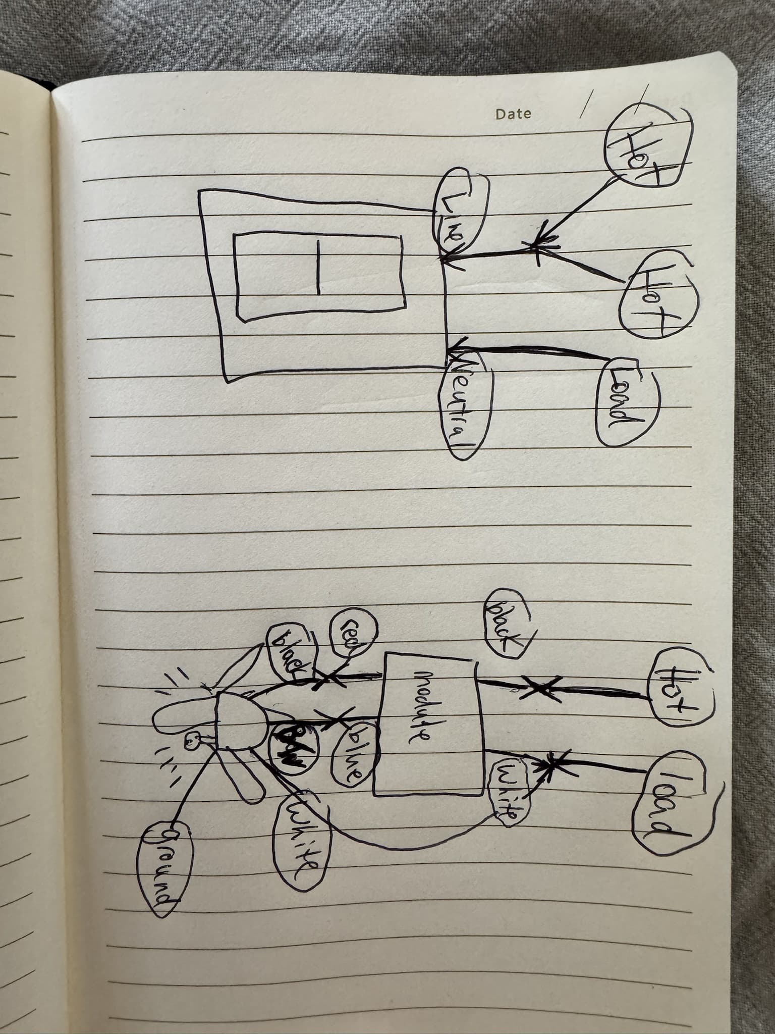
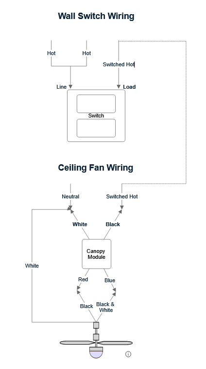
I’m hoping someone can help me troubleshoot my setup. I’m installing the Blue Inovelli 2-1 switch with the Blue Fan canopy module, and I followed the No Neutral + Smart switch wiring instructions from Inovelli’s site (Fig 1) as closely as possible. But I must be missing something because:
The switch doesn’t power on
The canopy module is not pairing
Power cycling at the breaker, or pulling the air gap tab at the bottom of the switch changes nothing.
What I’ve tried so far:
For a week, I only had the switch installed and had the non-hot wire (currently in the Neutral terminal) connected to the Load terminal instead — the switch worked as intended to power on lights.
After adding the canopy module and moving that wire to the Neutral terminal (per my understanding of the instructions in Fig 1), the switch no longer powers on.
Strangely, right after this change, the canopy module did pair and stayed paired for ~30 minutes — but the switch was unresponsive, and now nothing works at all.
Current Wiring Setup (overview in Fig 2)
Wall Wiring (to Inovelli 2-1 switch) Fig 3:
Two hot wires (from box) pigtailed → Line terminal on switch
Non-hot wire (from box) → Neutral terminal on switch
Ceiling Wiring (from house to module):
Hot from ceiling → Black on module
Non-hot from ceiling → White on module + White on fan
From module to fan:
Red on module → Black on fan (fan motor)
Blue on module → Black & White on fan (lights)
Additional info:
The two always hot wires on the wall, when connected, power on the rest of the outlets and lights in the adjacent room. Since both need to always be connected to supply power to that room, I reasoned that they should be connected and pig tailed. However, would one of these be better off in the “Traveler” terminal?
In Fig 2 I call non-hot wires, “Load” wires. Both terminologies are probably wrong but it sounded more clear to me to label them as “non-hot” in the “Current Wiring Setup” section.
When I pull the air gap tab at the bottom of the Inovelli 2-1 switch, the LED strip briefly flashes light blue for a second, then dark blue for another second, followed by red/orange for a second, before turning off completely.
Does anything look off? Is there anything I should test, rewire, or try differently? I really do not want to run any new wires if at all possible (one of the main reasons I chose Inovelli).
Appreciate any tips or guidance. Thanks in advance!
We’re just going to start at the beginning by troubleshooting your switch first. You used the proper diagram, but we need to make sure you followed it properly. The switch should power up properly, but doesn’t, so there are a couple of possibilities. 1) You didn’t wire at the fan box properly or 2) You damaged the switch by plugging conductors into the wrong terminals. Either way, we’ll figure that out. We will do this in small steps.
You only have 2 conductors in your switch box, so that is what is referred to as a switch loop, with the hot and neutral originating at the fan box. If you re-wired at the fan box properly, you will have a hot and neutral at the switch box.
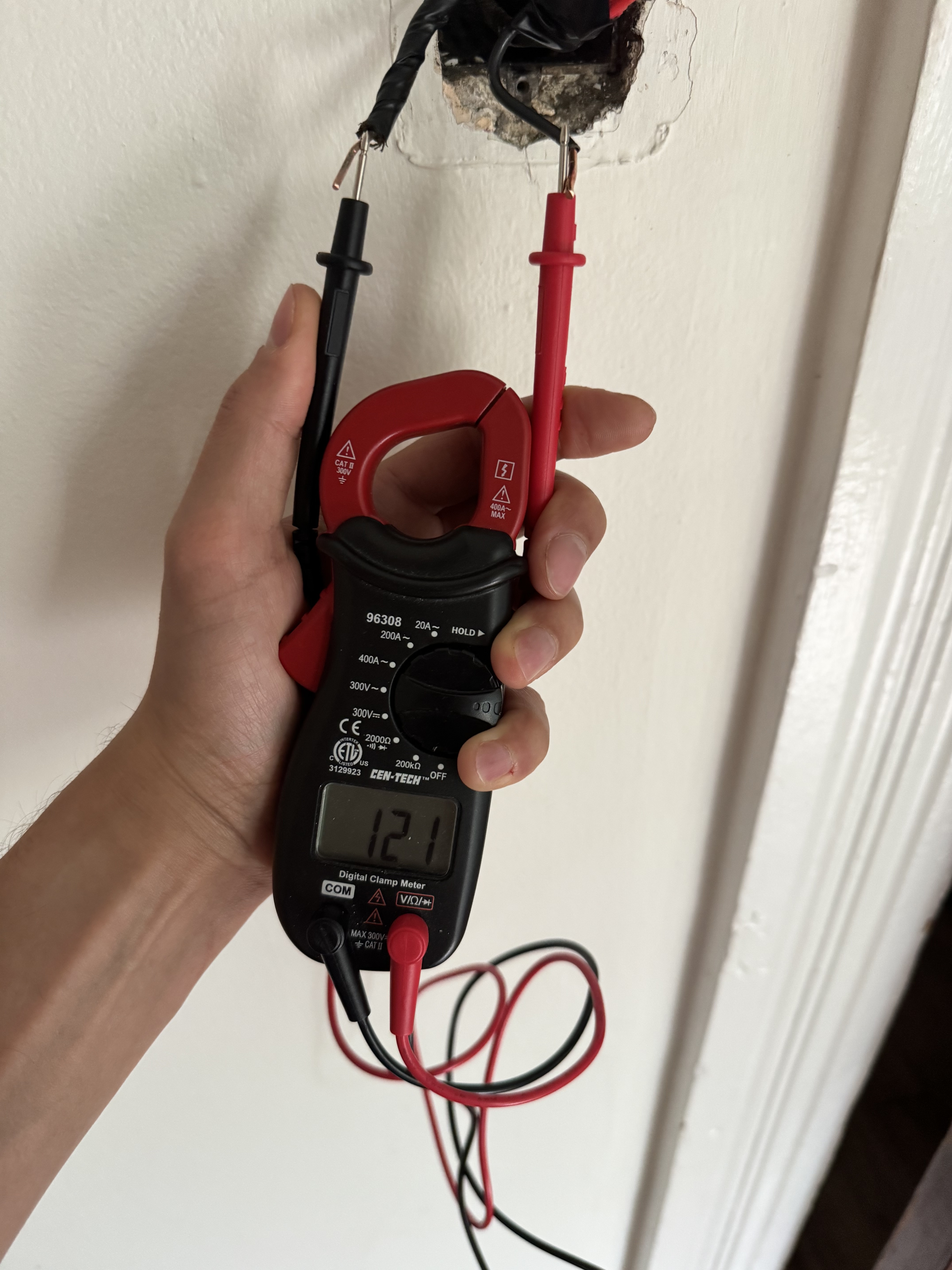
Do you have a meter? Not an not a non-contact voltage tester, but a meter that will measure the voltage. Disconnect the switch from the wires. Using a meter, test betwen the two conductors with the meter set to measure AC. What what is the voltage? Please take a picture of the results and post.
So now let’s figure out which conductor is hot and which is the neutral. Hopefully the box is grounded. Test between each conductor and the metal box. One should be 120VAC the other should be about 0. The one with the 120VAC is the hot. Let me know which is which!
If you’re getting nothing on both, then your box isn’t grounded and we’ll go another route.
Yep, I thought that might be a possibility. Do you have a non-contact voltage tester? That’s a pen like saying that buzzes when it senses voltage. Using one of those, one of those conductors will buzz as hot and the other will not. That’s about the only way I can think to identify which is which at this point.
Okay thanks. The red hot pigtiled one goes to the line on the switch and the other conductor goes to the neutral. Switch should power up. Let’s see what happens.
That is how you have it in the picture you posted but let’s try it again
I made a video of me wiring it now. I wired it live so that I could get the blinking lights in the shot. Light blue, dark blue, off with no light reaction on button push thereafter.
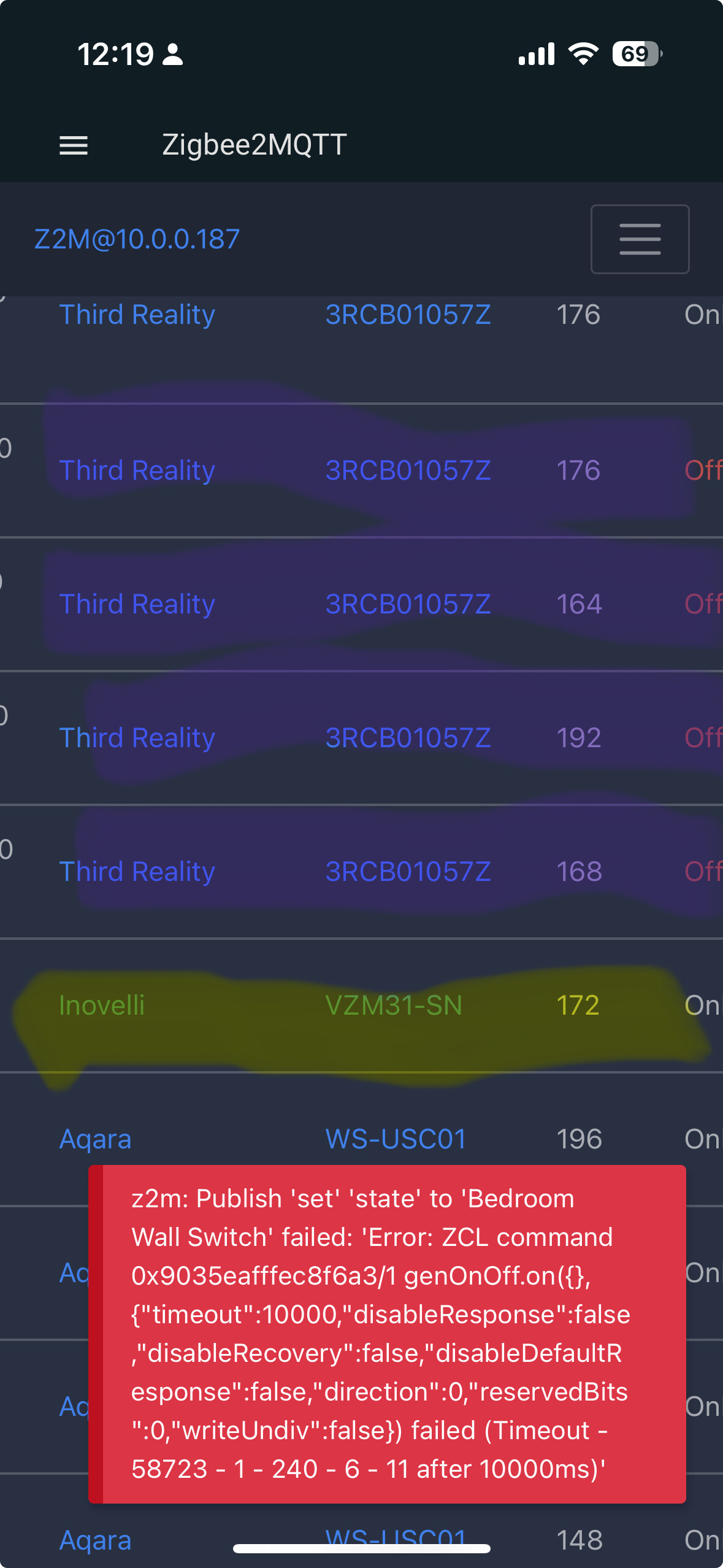
The switch shows as online in Z2M right now (yellow in picture below). But the lights connected to the canopy show as offline (purple highlight in pic below).
I tried changing the state of the switch in Z2M from off to on, and you can see an error message on the bottom right of the picture as well.
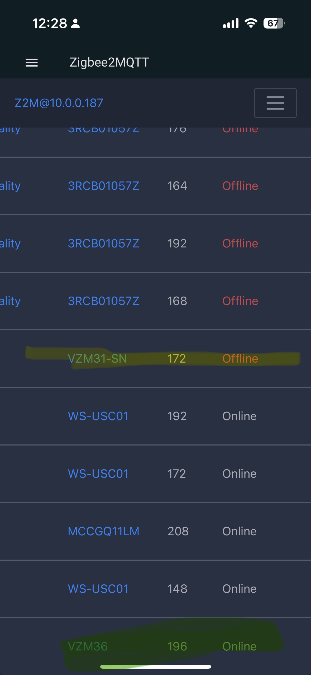
It’s been ~10 minutes since I reconnected and now the switch is offline in Z2M (yellow in pic), and the canopy module did actually pair to Z2M and is showing online (green in pic)
Okay. Trying to do one thing at a time. We’re still working on the switch.
Does the switch look normally powered up? Referring to standing in front of it looking at it. Do you have the blue LED bar when it is on and if you press the down paddle does the lead to more turn off?
First of all, don’t EVER wire a switch like that. I don’t know if you realize it, but your screwdriver is hot when you’re touching the line screw wiring it hot the way you did. No one here wants to see you win a Darwin award.
I understand that you want to watch the switch boot. The proper way to wire a switch is to cut power to the circuit at the breaker. Wire the switch and put it back in the box. Turn the breaker on. Then, pull the air gap and push it back in effectively rebooting the switch. You will be able to see it power up.
From the tail end of the video it looks like with the switch powered up you are not getting the proper LED bar display. The switch may be damaged.
I would factory reset the switch. Then reboot it using the air gap. When the switch starts back up it should be pulsing blue. If it’s not, try pressing config 3x. If it is pulsing blue add it back to your hub. You should see green on the LED bar when it is successfully added.
Even without a load, when you press the up paddle the LED bar should display fully. And when you press the down panel, it should turn off.
To factory reset push the on (up) portion of the switch and while holding the up push and hold the configuration/favorites button until the LED bar turns red then let them go. You should get the reboot color pattern on the LED bar.
The Inoveli switch doesn’t work in this set-up, no matter what I try, so I tried an Aqara no neutral and it works now. I’ll keep the 2-1 switch for another room and the canopy here with the Aqara
@kunzcw you may have multiple issues with the drawing and if the switch is wired as drawn your canopy module and or switch may prematurely fail as the dimmer switches are not designed to handle inductive loads. The canopy module should be provided a constant hot or be wired to a switch that can handle inductive loads. I highly recommend an electricians assistance at this point. Knob and tube wiring is/or can be dangerous if you are not experienced in working with it. I would also recommend staying away from smart bulbs until you have them both functioning correctly to help minimize your frustrations.