Your right, I missed that.
I’d open up the fixture and add that into your diagram. I suspect your actual line is coming in from there.
Sorry for the crude edit, I only have paint on the office pc so I had to use an online editor.
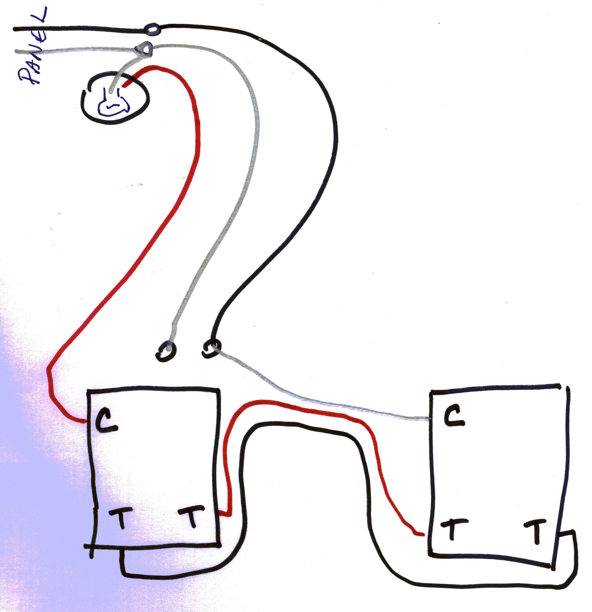
This is what I’m seeing here as far as wiring goes. I still suggest to pull off the light fixture to confirm the power source is up there. I also still suggest taking the white wire in switchbox #2 and confirming it has constant power as well.
The only issue with the light fixture is that they are LED recessed lighting mounted up in the soffits outside. Will be a real pain in the ass to get to. I’ll double check the white wire in the 2nd switch though to see if it has constant power.
So my understanding would be as follows then for now wiring it up.
-
Run a small “jumper” from that white, black. white bundle (my constant hot) into the “LINE” on the Innovelli (as this is my constant 120v according to my multimeter)
-
Run the red wire from “A” in my diagram into the “traveler” slot on the switch
-
Run the black wire from A into my “LOAD” slot on the switch
-
Tie in another white jumper into the “NEUTRAL” bundle that is wire nutted currently from B and C.
That leaves the red wire from B that is currently in my switch with nothing to plug into. Just wire nutt that off?
I’ve never hooked up a smart switch with a dumb switch before, in my head it just complicates matters. I would personally use an add-on switch in this scenario.
One thing I will note, if I’m correct on the wiring diagram, the red wire from B is the load wire that connects back into your light. If you don’t have it put in there somewhere then the light would never turn on.
Ahh that makes sense. I think what I’ll do is try this.
Red from B goes into my “LINE”
Red From A into “Traveler”
Black From A into “LOAD”
Jumper wire from the 2 white’s that are nutted together into the neutral.
That should in theory work…I think…
The reason I went with the Inovelli’s was because they didn’t’ require an aux switch. Wouldn’t it kind of defeat the purpose to have to be more aux switches everytime you want to put in a smart switc?
3 reasons I’d use an aux switch.
1: My OCD would be out of whack if I had 2 switches that behaved differently, and I hate having a switch that’s in the off position while the light is on.
2: They’re only like $30 CAD, I’ll pay that to not hate the switch because of reason #1 lol
3: They’re much easier to wire. You need 2 wires, neutral and traveller. So in your case here, you’d take the 3 wires going from box 1 to box 2. Cap off the black on both sides. Wire the white into your neutral bundle. Wire the red into the traveller of the inovelli switch and then hook the inovelli switch up like normal. No messing around with trying to figure out this wiring scenario (which in your particular case is not the most common way to wire 3 way switches)
So I tried again tonight and can get the switch to turn on, but as soon as I flick the other switch (switch 2) the inovelli dies and I no longer can control the lights.
As per folks comments I went into the switchbox 2 and tested the voltage with a volt meter. As some of you suspected the white wire is hot (constant). Odly enough (and this may be important) if I flick the switch in swb1 the black and red wires alternate to 4.0 volts
So switch up (in swb1) I get white as 120v and red as 4v and switch down (in swb1) I get white as 120v and black as 4v
Not sure what to do at this point
There are a number of things I would suggest:
- I would remove the marret from the W-B-W and measure on which wire the power is coming in on.
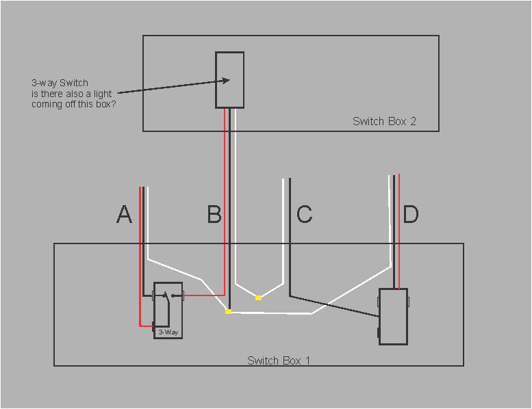
The current switch has common written on the bottom of it.So in this case it’s the red wire from A in my diagram in switchbox 1 that goes to the common slot on my current 3 way switch.
- I would recheck the wiring on switch A1 if it is wired like you posted the wiring makes very little sense. It would mean when switch A1 was toggled:
Wire A-Red would alternately be connected to
- Wire A- Black
- Wire B - Red
-
I would check the wiring in switch in Box 2 for which is common.
-
In box 2 the label “2nd light for exterior light switch” I’m not sure what you mean “2nd Light”.
I know this is a PIA however I started posting here because I recently installed a smart dimmer (Inovelli Gen1), it required a neutral. It took me some time to sort it out and I understand the wiring.
To trying to sort this out by back and forth posts and with a couple of folks helping can be tedious. The only thing I can say is there will be a solution ![]()
UPDATE
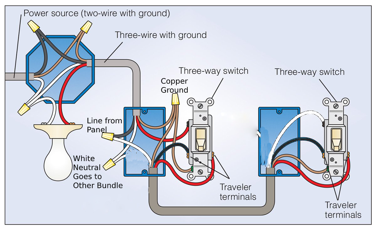
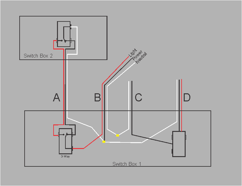
I redrew your sketch, not because yours was lacking but I wanted to add in the existing 3-way switch internal connections. Its the only way I can follow the circuit.
Super appreciate all your help! My girlfriend thinks I am. Crazy but I hate letting situations like this get the best of me. I am determined to get it working.
To answer your question there are no other lights in switch box 2, only the 3 wires I’ve shown going directly into then 3 way switch. There is one other switch in that box but it’s a single pole switch for the garage lights which is actually on a separate breaker circuit all together.
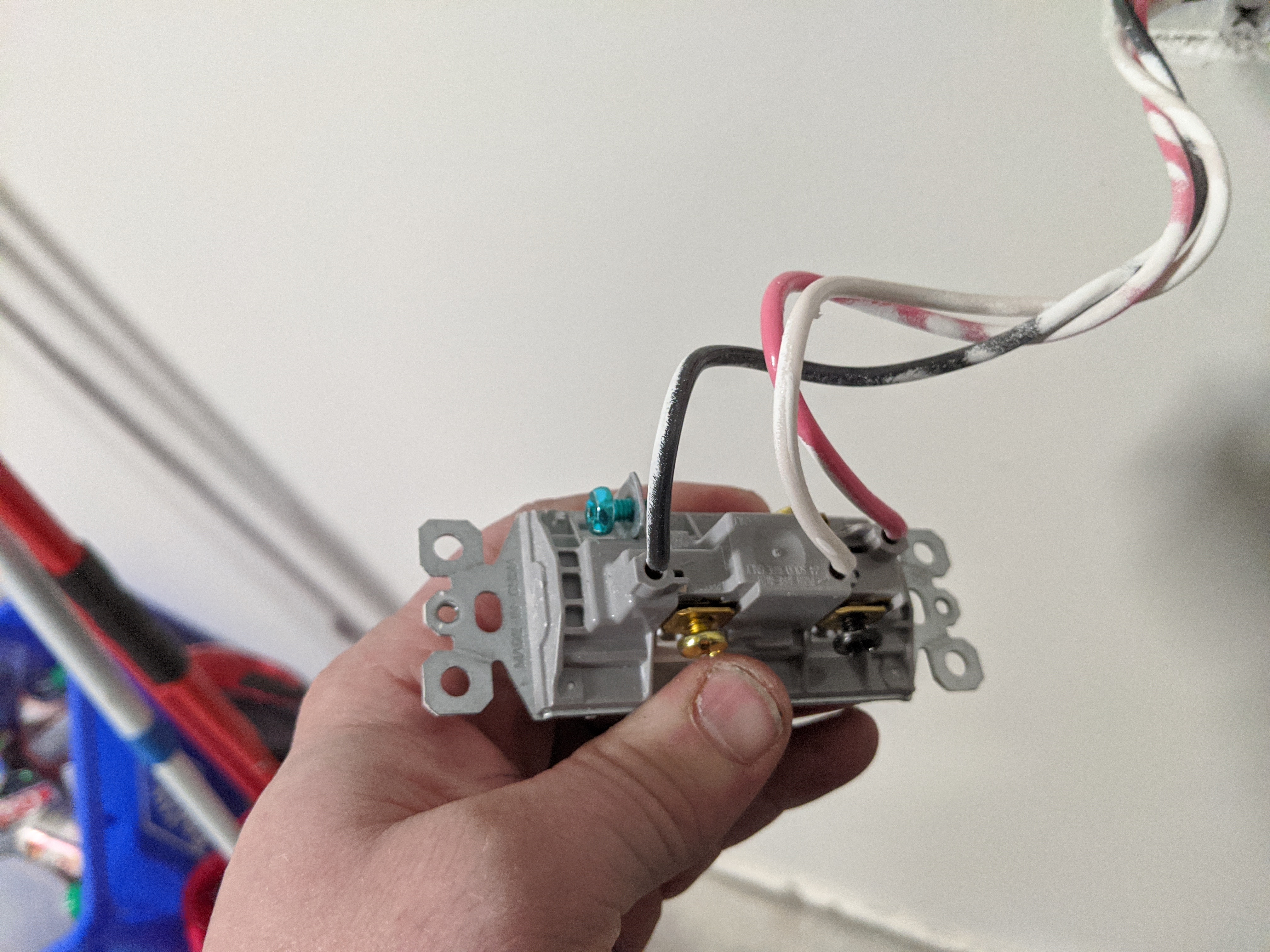
In switchbox 2 the red wire goes into the “common” slot on the switch, and the white is a constant 120v according to my multi meter as I mentioned earlier here is a photo of that switch in swb2
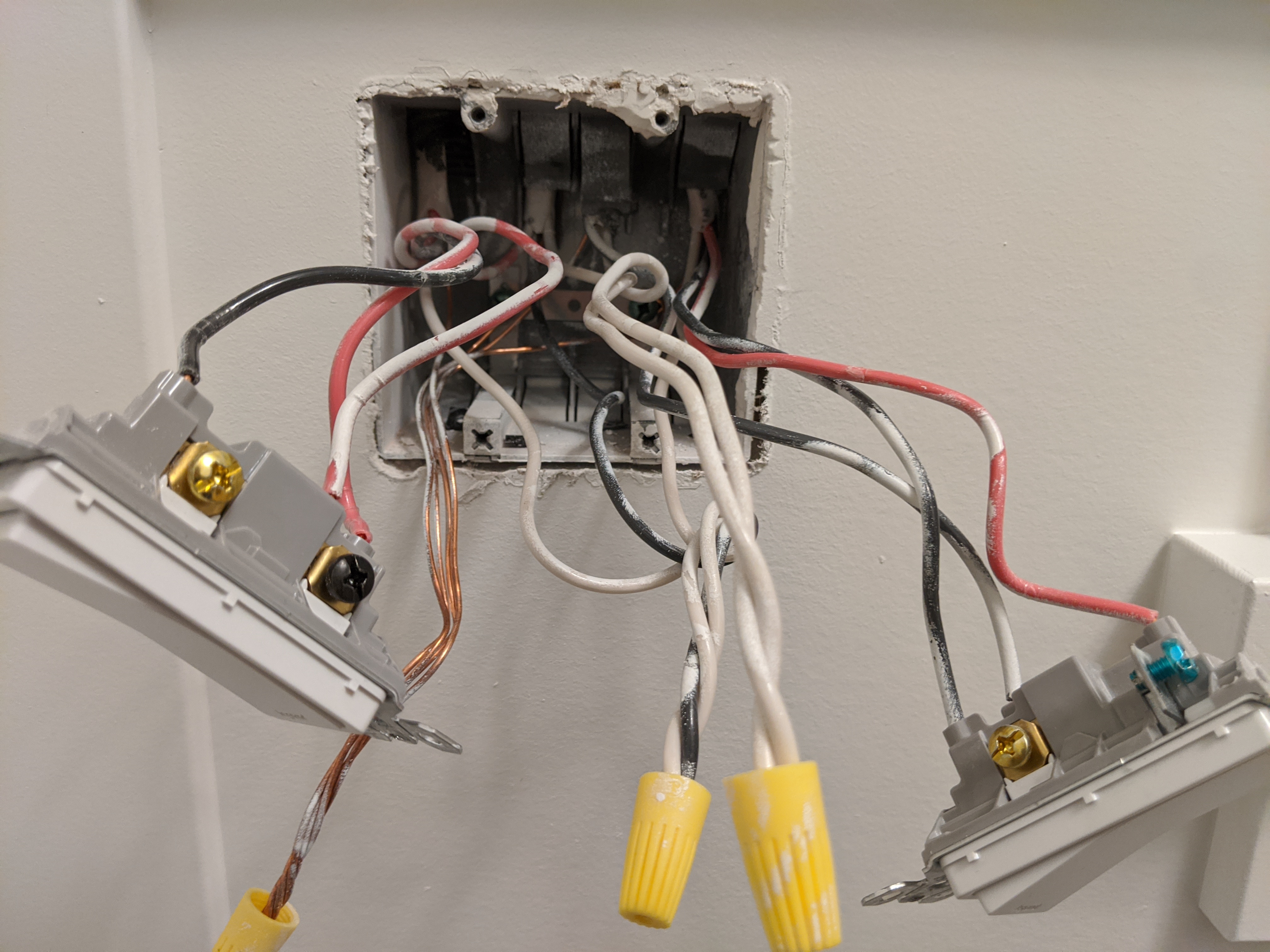
Your diagram is accurate, and my apologies you were correct. The red wire from A is in the common slot in switchbox1. Here is a photo of that again as well.
Thanks for all of your help everyone! Super grateful
I will have to check tommorow, but I suspect you are also correct about the hot wire in that WBW setup being the black wire. I think that 2wire from C has the white as hot which then I goes. To swb2 and comes. Back as hot black. I’ll try to update your schematic tommorow when I get a chance to show the voltages of. Each wire in each switchbox
That’s switch #2 in your hand in the top picture, right? The white is going to the common, NOT the red. The common on that switch is the black screw.
What’s happening is that the hot is being sent to box #2 via the white, which is why it’s bundled with the blacks in box #1. So what I think you may have is the leg starting in box #2. Power is fed to the box via the constantly hot white on the 3-wire. The red and black are travelers back to box one.
If I’m correct (it’s hard to see from your pic of box one), the red and black are the travelers in box #1 and they are connected to the two brass traveler terminals of the switch in box one. The common black screw on the switch red goes to the light which is the switched lead.
I think power is coming from the light but not connected to it, which is why it shows up via the thee-wire.
So maybe the dimmer goes in box #2 as the source of constant power is there. As I’ve said before, the key to these is to find the constant hot. There is a constant hot in #1, but it’s not wired directly to your leg.
I’d still hunt your electrician down and ask him what he did!
@Bry pretty sure you drew the same diagram I put up LOL glad someone else is seeing it too.
There’s going to be some re-wiring required, but I think I’ve got it figured out. I can picture it in my head just trying to put it down into words.
I’m sorry, I certainly didn’t mean to steal your thunder. I recall you saying power was coming from the light and I agreed. Didn’t fully get my head around the logic until just now.
I’m not understanding about the re-wiring. My diagram is what is there now and at least in my mind, that ought to work.
The switch can’t go into box #2 because you need a neutral to use a dumb switch in a 3way. So the white wire that feeds power to box #2 needs to be unhooked from the bundle and repurposed.
I follow that, but if you re-purpose the white then you’re just left with travelers in box #2. There was discussion about using an Aux. Doesn’t that do away with the requirement for the neutral in box #2 then?
Or in the alternative, you could re-wire to not “send” the hot. That just makes my head hurt again.
I THINK this should work. Again, I’ve never used a dumb switch with a smart switch before.
SB1
-Remove white wire A from BWW bundle and add a jumper (preferably black) from the bundle to the LINE of the inovelli switch.
-Connect white wire A with red wire B using a marette. White wire A will be connected to the common terminal in SB2 and red wire B should be connected to the light. This essentially gives the common terminal in SB2 a direct connection to the light.
-Red wire A would go into TRAVELER on inovelli switch. This should already be connected to traveler in SB2.
-Black wire A woud go into LOAD on inovelli switch. This should already be connected to the other traveler terminal in SB2.
-Add a jumper (preferably white) from the neutral bundle to NEUTRAL on the inovelli switch
Bry is absolutely correct, the common on the LeGrand switches are deceptive. You can verify the common by loosening the black screw and see which wire becomes loose.
So I looked at was going on and realized that the initial assumptions on A & B were not correct. The Key was the wiring of the 2 3-Way switches. I thought instead of burying the 3-Way function in this post I would create a new one… see Anatomy of a 3-Way Switch
This is what I believe you have:
To wire your smart Dimmer in the A1 position you simply:
A - black - dimmer Load
A - Red - dimmer traveler
These above two could be reversed with no effect.
B - Black - dimmer “Line”
B - white - dimmer Neutral
IMPORTANT:
-
You should get some bare #14 and run wires from the bare wire marret to the ground(green) wire of the dimmer. The electrician should have run the bare to every switch and receptacle green wire. The lazy ba__ard should loose their licence. And as Bry said their color choices are WRONG for just the reason you are having, by picking seemingly random colors for the different wire functions it makes any changes much more difficult.
-
Tell your girlfriend (nicely) that this is more of a learning experience than just installing a smartswitch

Let me know how you make out.
John
@JohnRob I got the same conclusion. The only thing I think you’re missing is
A - White connect to
B - Red
The common terminal from switch 2 needs to be fed back up to the light.
@Bry to wire an aux you only need 2 wires. Neutral and traveler. Having never wired a smart/dumb 3way, I only mentioned it because I knew how to wire it right away.
For an aux switch
A - White - add to neutral bundle. Goes into Aux neutral in SB2
A - Red - Inovelli traveler and Aux traveler in SB2
A - Black - cap off on both sides, wouldn’t be used.
B - Red - Inovelli load
B - Black - Inovelli line
B - White - Inovelli neutral