Having a hell of a time getting this going here. I have a brand new home and orderd a bunch of Z-Wave Gen2 On/Off Switches. My plan is to automate a bunch of my lighting with my Hubitat hub.
The issue I am having is setting up my wiring. All my switches are a 3-way setting, with a dumb switch on one end. I can’t seem to find my particular scenerio in the wiring diagrams provided.
I’ve attached upclose photos + labels of switch box 1 and switch box 2. Ignore the switches on the right of each switch box as those are unrelated (different lights). In this case the 3 way switches are the left switches of SWB1 and SWB2.
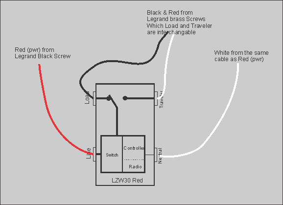
I tried hooking it up as the AS the RED Wire from #1 in SWB1 as my “line” ie hot (as I test it and this had 120v. I hooked the BLACK up to LOAD. I hooked the 2nd red wire (red wire from #2) on SWB1 into my “traveler” as this looks like it goes over to the dumb switch. I then hooked up the white wire to jumper onto the 2 white neutral wires that are bundled together in SWB1
I flipped the breaker and I saw a blue LED and the switch worked to control the light, but the other switch in the garage now no longer controlled the lights. IE it didn’t work as a 3 way application anymore. Can’t figure out why.
Am I hooking this up correctly? Any help would be greatly appreciated. From what I understood I only need the smart switch here and didn’t need any “add-on” switches on the other end where the dumb switch is.
Here are photos as it won’t let me upload more than 1 photo (says new user can’t only upload 1)
You are going to have to start by properly identifing the line, which is the source of power. Your first picture in position one from the left shows a 3-wire identified as the line. That’s likely not correct, as it would be unusual for the line to be fed by a 3-wire in this circumstance. You stated that the red that you wired to the line was hot. When you throw the other switch, does it remain hot? At any given time in a three way, one of the two traveler wires is going to be hot, so just because it’s hot with the other switch in one position doesn’t make it the line. You are looking for a 2-wire that is constantly hot regardless of either switch position.
Given that’s a 2 gang box with 4 sets of wires going to it, I suspect the black on 3 is your actual line (and probably the only line in the box), and the wiring was done with electrician magic to supply power to both other branches. My second guess would be 2 carries the line on the black and red, but that’s unusual as Bry said.
This would be one of situations I’d recommend bringing in an electrician unless you can determine for certain what is going on.
don’tcha hate it when the paint guys don’t mask the boxes correctly. I have a box where a black wire is nearly all white from the paint.
In general power coming into a box like this is from a two wire cable (i.e. no red). That is unless it goes through another box previous to entering the box you are working on.
However I’ve seen enough odd wiring situations (even with new homes) that I would not categorically discount any configuration.
Since you bought a “bunch” of switches I would suggest you get a voltage tester. Either a meter or something like this Tester. I would recommend the type I linked to for two reasons:
you only need two hands to use it, with a meter you must also support the meter body.
There is a one probe non-contact type that some folks have claimed to have good luck with, however I’ve also heard others complain it provides false positives in boxes with cramped wiring.
Can you share the original switch wiring with us? If you draw a diagram you might use a dashed line for the white and you should ignore (not draw) the bare copper safety ground wires as they go everywhere.
Thanks everyone for your responses. I haven’t’ found a single 2 wire (black + white) lead going into the any of those boxes yet. It always 3-wire. The only thing I can think of is that a 2 wire goes straight from the power source to the lights, then a 3 wire to the swithces, but that’s not common is it?
I did use both a multimeter AND my power wand to see where my power was. If I remember correctly (will need to double check) the RED wire from #1 in Switch Box 1 is HOT. So it had 120v. When I flick the dumb switch in the other room the OTHER red wire would then also be 120v. So that Red wire (1) from Switch Box 1 seems to be constant hot.
That’s actually a common scenario. It depends on the electrician’s habits and sometimes whatever is easier. For example, if that is going to be on the end of a run, it might be easier to go to the light first instead of the switch, if it’s closer.
In a normal power-to-the-light scenario, however, there would typically be only one 3-wire connected to each of the switches. That’s not what you have though.
It’d difficult from your pics to see exactly what’s going on there. Plus that black connected to a white probably neutral bundle is even more confusing. Since your home is new the electrician ought to be easy to find. I would go grab him/her and get some assistance.
I think you could spend a lot of time determining exactly which wire was what. Probably something I would do. However if your goal is to simply replace the 3-Way on the left side of your first picture it is really quite easy.
Its nearly the same as the current LeGrand. The only difference is the addition of the white Neutral to help power the switch radio.
Hey John,
That’s pretty much how I wired it. I had the “traveler” as the red from the 2nd wire and the black as the load. For the neutral I ran the short white “jumper” over from the 2 connected white wires. You’re saying in this case I should just bring the neutral straight in from that 1st 3 wire? Ie no jumper line from that bundle?
I think that may work! I 'll give that shot when I get home.
You can get the neural there any way you can neatly wire it. I only specified the first cable because I know that is the neutral you need to connect and wanted to be ultra clear.
Thanks for the help so far everyone! I’ve done some more research on this thing tonight again before I tried hooking it up. I am not sure if this helps or thickens the plot.
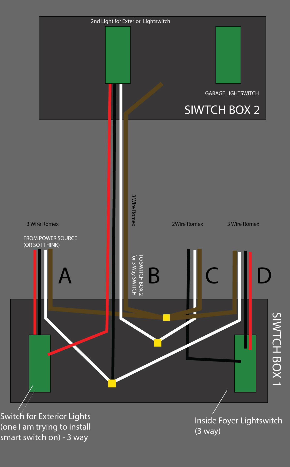
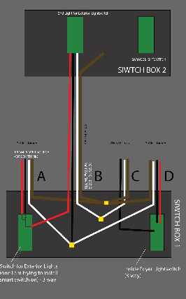
I went in with my multi-meter this time to see what is coming in as “constantly hot”. I’ve also put together a clearer wiring diagram that shows all the wires and what they are doing.
See attached diagram.
If I put my multimeter on there. The only wires that actually ever show as all hot are the group of wires held together by a marret. The WHITE,BLACK,WHITE wires that joins together from ABD in my diagram is constantly hot no matter which way I flick the switch in Switch Box 2. So for example the Red white on A in Switch Box 1 will read 120v as well as the group of 3 wires (WBW). If I turn the switch the other way in SwitchBox 2, now the BLACK wire on A in SWB1 will be 120V, and the group of wires also 120v.
I feel even more confused now lol. Anyone see what’s going on here?
I also discovered there is a 2 wire romex coming into this box, but it doesn’t seem connnected to that switch except for the one 1 wire which runs to the group of switches in the other box. (scratches head)
Well… it does me us think.
It would help if we knew the wiring for the 3-Way. Can you look for something on the switch that says “common” or perhaps one terminal with a black screw?
You measured constant power at the White-White-Black junction, regardless of the positions of any switches. We must find which wire is actually the permanently “HOT” My money is on the black wire tied to those white wires.
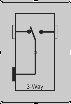
3-Ways are really simple…
BTW what’s a marret? I’m assuming its what I would call a wire nut, but I’m curious about the term you used. I’m in Connecticut so perhaps its a regional thing.
Yep a marret is just a wire nut. Not sure why we call them that up here in Canada but seems to be a thing.
The current switch has common written on the bottom of it. So in this case it’s the red wire from A in my diagram in switchbox 1 that goes to the common slot on my current 3 way switch.
I was thinking C with the 2 wire romex…but now I’m confused. There should be a common on both switches. One with common would be from line, the other common should go to the the light…or at least in my 3 way setups with line and load in separate boxes.
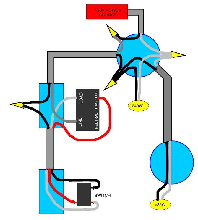
If this is a 3-way setup with power to the light, then the line wire should be the black wire that’s in the 3-way bundle. The red from that bundle would go to the switch and the white would be neutral.
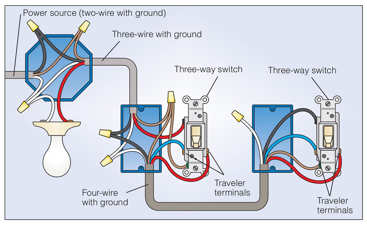
Easiest way to tell would be to pull the light fixture and look at the wiring there. I’d almost guarantee your 14/2 from the panel is going into there. The black will be joined together with a marrette and the white will be going to the light. I’ll try to find a diagram
I can’t quite find exactly what I’m looking for, but this one is close. This diagram is using a 4-wire romex between switches instead of a 3-wire with the neutral tied off with a marrette. Your neutral is tied into a neutral that feeds another box somewhere along with another white wire from your foyer switch bundle which would be carrying power.
In your case, the black wire coming from the light is tied into the white wire going to the switch. To confirm this, if you pull the white wire in box #2 you should have constant power. It should also have black tape on it to indicate power but in my limited experience I’ve found it’s a corner that’s often cut.
@GregW I’ve actually encountered this in my house where the run was a non-neutral situation. That was one of those cases where line went straight to the lights and not to a switch first.
A wiring setup like this is kind what you were thinking? (note, this setup had to be modified with an aux switch at the dumb switch location since it was non-neutral, but this was the original setup).
I don’t agree. I drew the 3-way switch on your diagram. I can’t reconcile the wiring shown to date.
From your measurements:
Power comes in on: A-Red
3-Way Switch A can send power out on A-Black or B-Red.
I just can’t see how the wiring might work"?".
Question: When you checked for the Hot wire, did you remove Switch-A?
Could you check which wires are connected to the SwitchBox-2 and identify the common terminal?
And while you are at it pls check the wiring on Switch-D.