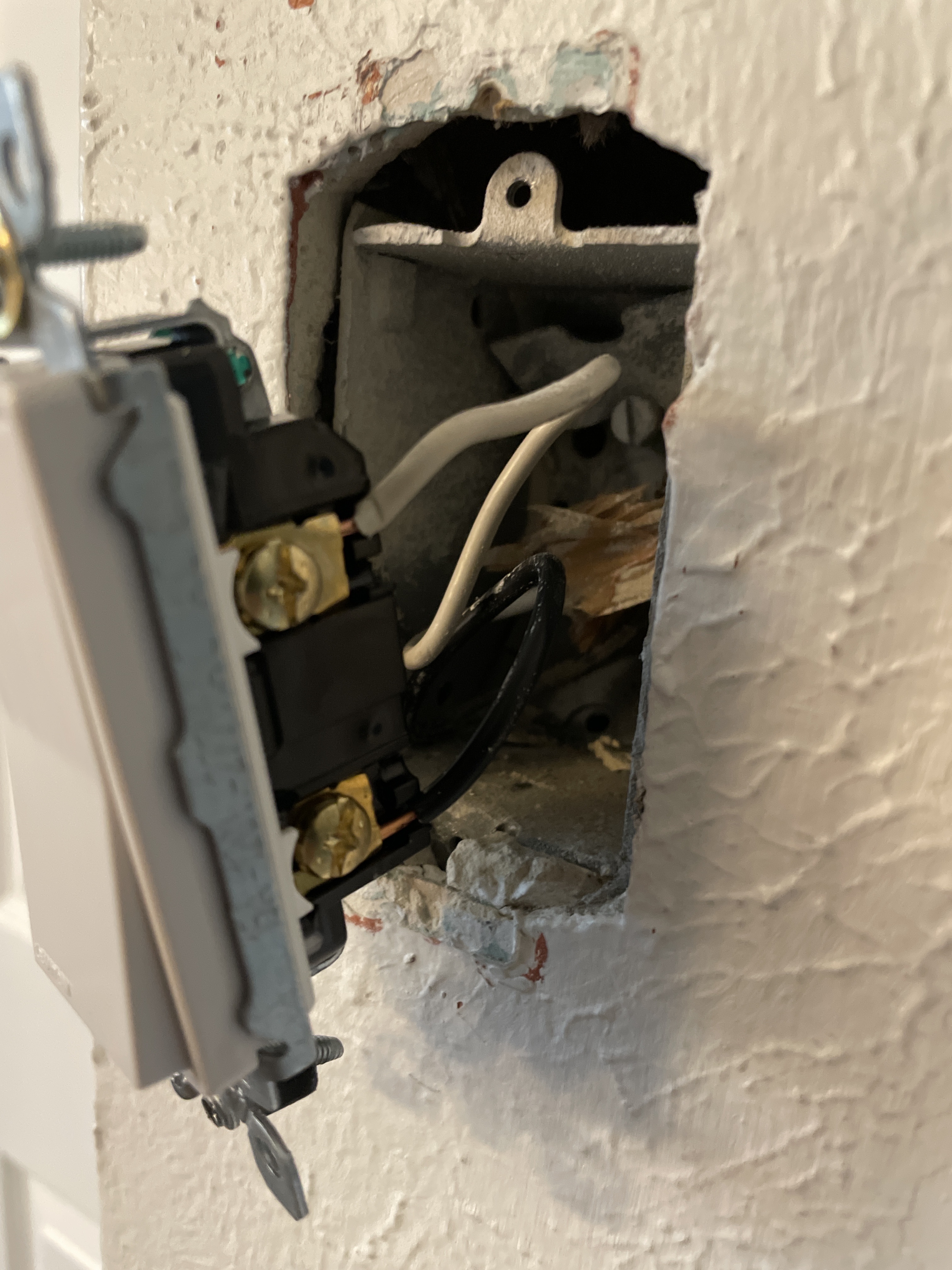
House built in 1963. In the switch box there is a white and black wire, both are hot. Because of this I assume power is going to the Hunter ceiling light/fan and then a separate set of wires are going to the switch box. Since the on/off wouldn’t work without a neutral, I connected the dimmer switch using the single pole wiring diagram but when turned on, the fixture makes a quick buzzing sound and then dims to a lower level. On the switch the blue light in the dimmer bar flickers and the switch is unresponsive.
In this switch box, is there only two wires - one white and one black?
Before you installed the Inovelli, what was in there? How was it wired?
What method did you use to determine that both the black and white are hot? Did you disconnect everything in the box before testing, or was there still a device connected?
Did you use a reliable voltage meter to check each wire against the grounded box? Is the box grounded?
Have you tried using the same volt meter to check a normal house outlet to confirm it is working correctly?
Thanks, so it looks like there is only a single black and a single white conductor in the box (can’t see if it’s Romex)?
Do you have a meter to test? A proximity tester won’t work for this. Remove both conductors from the switch and test between each of them and either the bare ground wire or the metal box. I’m guessing that one will have 120V and the other won’t.
EDIT: It looks like you have a switch loop based on your last post. The white is probably hot and the black is probably not. But best to test with a meter first.
Uploaded picture of current wiring, I reinstalled the original switch to start over.
Using a Klein pen tester, the one where you just touch the wire and it indicates green or red. This box is not grounded - there are grounds elsewhere in the house but typically in outlets, not switches.
I checked other “live” sources to make sure the tester was accurate. As far as I can tell it is working as indicated.
I don’t have a multimeter, I’ll go pick one up today and post the results.
Switch loop makes sense - since we’re here I am also trying to wire a 3-way switch to a retrofit LED recessed light.
The current two dummy switches have three wires in each box - black, white, red. I did the retrofit and the power is to the light with the wiring pigtails all above the fixture. I know more information is probably needed but any advice for this situation. I saw another post about “Power into light, no neutral in box” setup so along with the bypass I probably need an add on switch right?
Well, it’s not good that the box isn’t grounded both for safety and testing purposes. If you don’t have a meter, how do you know the box isn’t grounded?
In any event, the way to proceed is to determine, using a meter, which of the two conductors is hot. That conductor goes to the line on the Inovelli and the other to the load. This is a non-neutral, so you may need a bypass at the light. You’ll also have to set parameter 21 to non-neutral.
So the white is the 120V, you were totally right about it being a switch loop. Most of the single pole wiring in my house is set up the same way (as I now know).
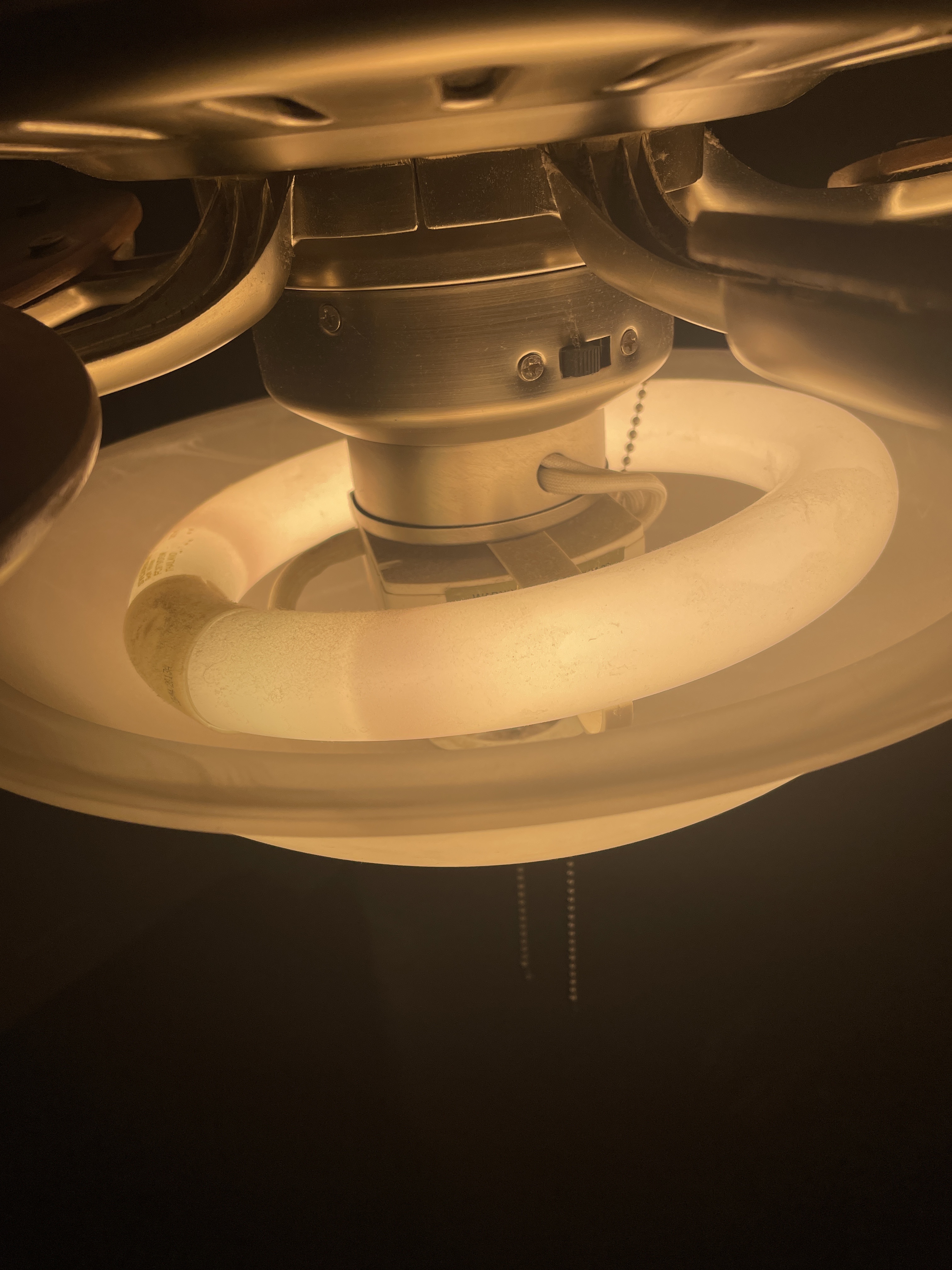
I installed the dimmer switch with white-line and black-load. It turns on but dims when activated and the switch is still unresponsive. I took the cover off the light and the ballast says it’s a 22W light. When I activate the fan, the light goes to full brightness and the switch is responsive (I assume due to the increase power draw). I figure this means I am going to need the bypass (ordered two already since this non-neutral and LED combination is going to reoccur). Let me know if this all makes sense!
Thanks again for all your help - I’ve gone through so many of your posts on this forum and you’re an absolute genius with these complex solutions. If you have a paypal, feel free to link it (if it’s alright with the mods), I owe you a beer regardless of how this all turns out haha.
Oh man. So what I don’t know is if the dimmer can be used with this type of bulb. This isn’t the typical CFL and definitely seems more ballast/starter. @Bry -What ya think with this type of light load? I didn’t even know they made these anymore.
Thank you for that kind offer. I’m glad to help out here. But if you have a local animal shelter and want to make a small donation, that would be great!!!
Now that I think about it, the dimmer isn’t rated for a motor load, so a dimmer may not be appropriate. This is the perfect candidate for a LZW36 fan light switch! That will work just fine as you can send a neutral to the switch box!
I think you may be right, I tried to install the dimmer to another ceiling light/fan fixture that wouldn’t need the bypass but still the switch started acting up; light would increase in brightness and then at max brightness would shut off and switch would reset. This repeated until I turned the ceiling fan on and on the highest speed setting was very slow. Overall, I don’t think the dimmer will work well with ceiling fan/light combos.