I am in the process of replacing all of my light switches with blue series dimmers, and just got to my first 3-way switch. The wiring I found was a bit unusual and did not match any of the diagrams in the instructions, and I was hoping to get some advice before proceeding.
For reference: house is located in Canada, built in 1989, all other switches have had a neutral wire in the box. I am installing a blue series dimmer model VZM31-SN, and have a white series aux switch model AUX01 for the second switch.
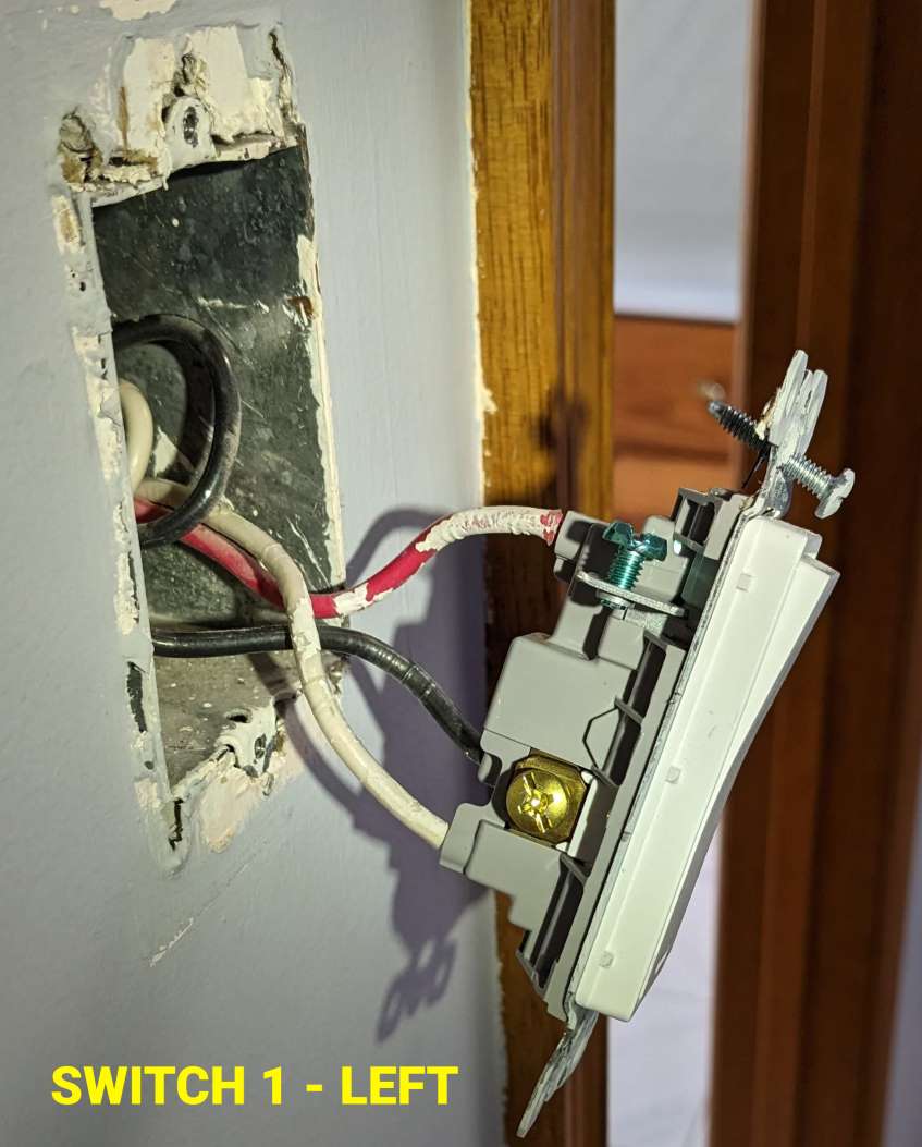
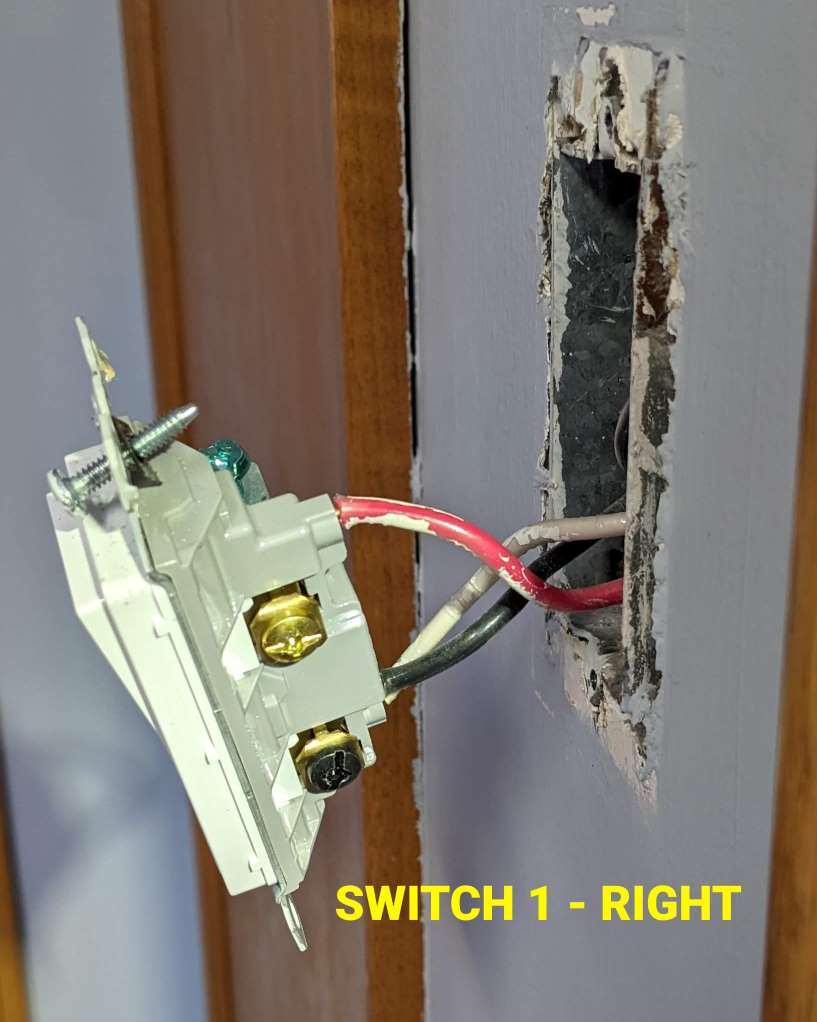
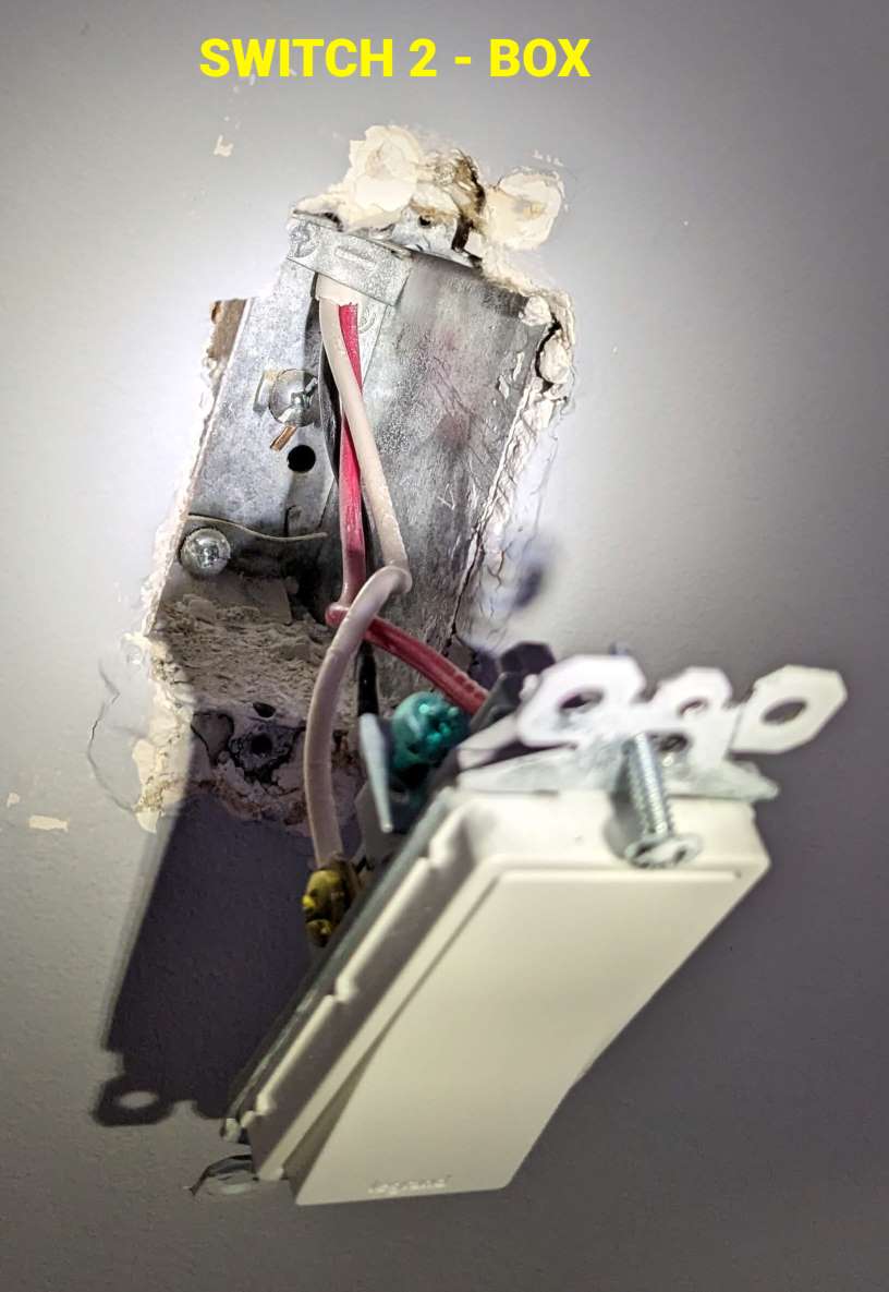
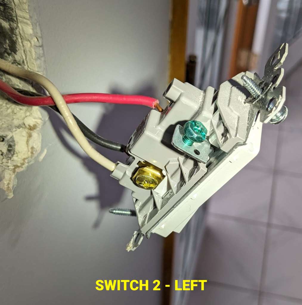
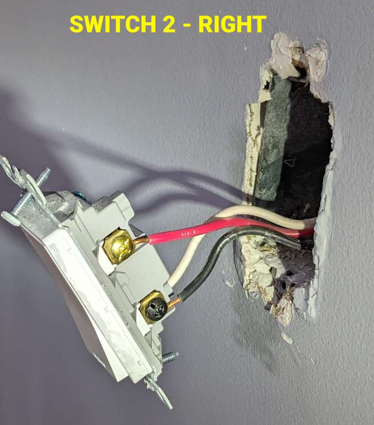
The light in question is above a set of stairs, with a switch at the top and a switch at the bottom. The switch at the bottom has one 14/3 cable entering, and the one at the top has a 14/2 and a 14/3. This switch controls a single overhead fixture. The light is on when the switches are the same state (both on or both off), and off when they are opposite.
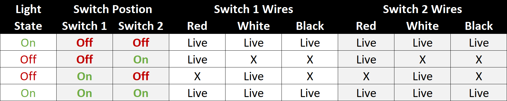
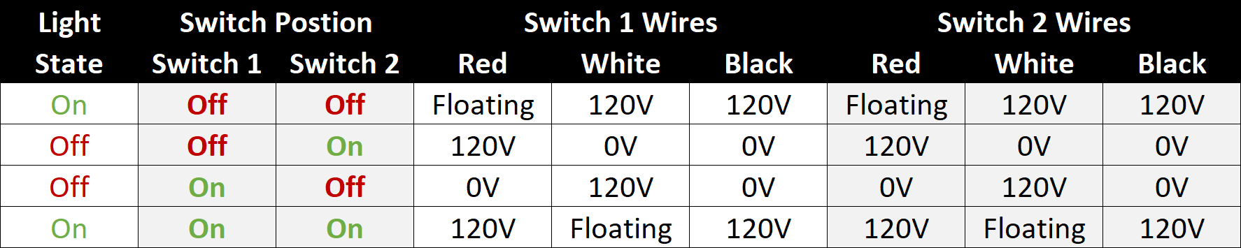
I did a bit of debugging, with my findings summarized in the table below:
Based on the 2 and 3-wire in one box and a single 3-wire in the other, it’s likely that you have a power to the box with the 2 Romex with the light(s) in the middle.
To test this, go to the box with the 2 Romex. Remove the black from the 2-wire Romex from the switch. USING A METER, test between that disconnected black conductor and its white conductor. If I’m correct, you’ll have 120 VAC there.
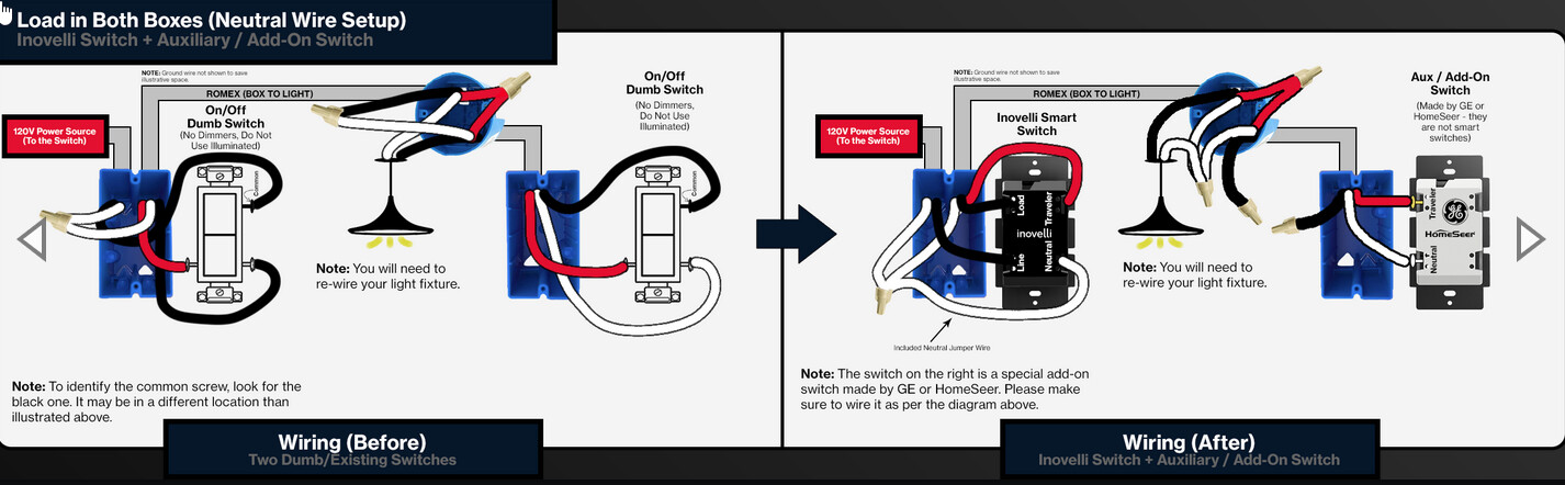
If that is the case, then the drawing below is likely what you have. The colors may not match exactly, but the concept will.
If you have confirmed this is your topology, one issue you may encounter is that you will need to get at the light wiring to rewire to accomodate the Aux switch. The Aux will require a neutral in the secondary box, which you won’t if it’s wired as I suspect.
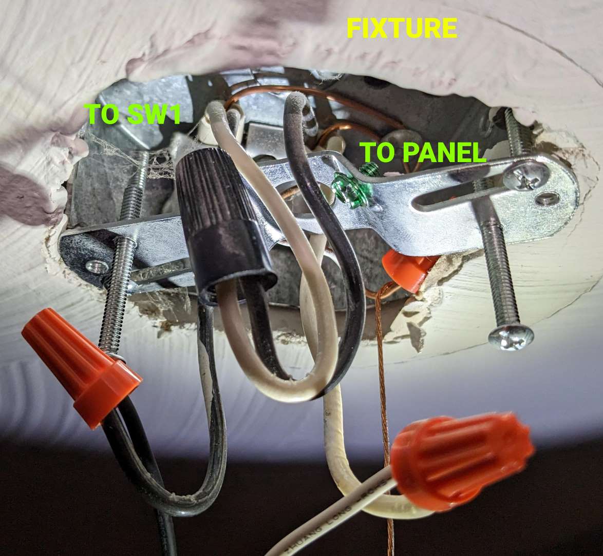
Thanks for the help, folks - it’s not the topology suggested, but after opening up the light fixture and taking some additional readings I did manage to figure it out.
@PJF You are correct, my table was wrong. I was using my meter in voltage check mode, and when measured to ground only some of the wires were 120V - one of the traveler legs floated between 60V-92V when both switches were on or off. This is the correct table:
@Bry I initially tested as you suggested and confirmed that there was 120V on the 14/2; except that the 120V was on white instead of black. Once I opened up the fixture box I disconnected the white-black tie there and found that the source was coming in to the fixture box, not into the switch box.
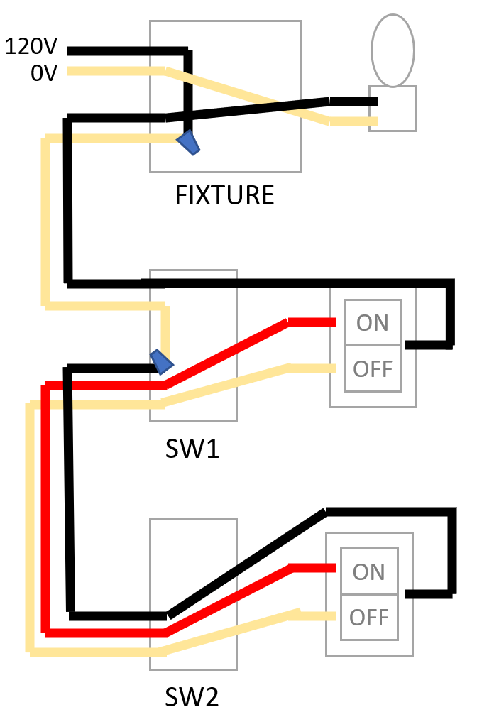
I’m pretty sure the topology is actually this:
Which means that yes, there is no neutral in the second box - and there is not in the first box, either.
Is the only way to make this work to run an additional 14/2 between fixture and switch 1 so that I can convert this topology into line/load in same box? There is an attic above the fixture so it is not completely out of the question but it would be a royal pain.
Yep, that makes sense. When power starts at the light, the common convention is to send the hot to the switch box over the white, using the black to return the switched hot to the light.
There is no need to run another Romex. You can wire this as a non-neutral with the Inovelli in SW1.
At SW1, connect the white hot from the 2-wire to the Line terminal and the black from the 2-wire to the load. Connect the red from the 3-wire to the traveler terminal. Connect the black from the 3-wire to the 2nd hole on the switch’s Line terminal. This sends a constant hot and a traveler to SW2.
At the SW2 Aux, connect the black to the Neutral terminal and the red to the Traveler terminal.
Depending on your load, you may need a bypass at the light.