I recently bought a new home and am looking to replace all the switches with Red + Dumb combinations - most lights are on 3-way circuits, so I bought one red dimmer switch to test it out before buying 15 more. I had an attempt at wiring it up yesterday - the red switch powered on and I could see the bar lighting up (also tried setting “dumb” config via the switch), but the lights would not turn on regardless of the position of the dumb switch and how much I held up or down on the red switch. What could I have missed?
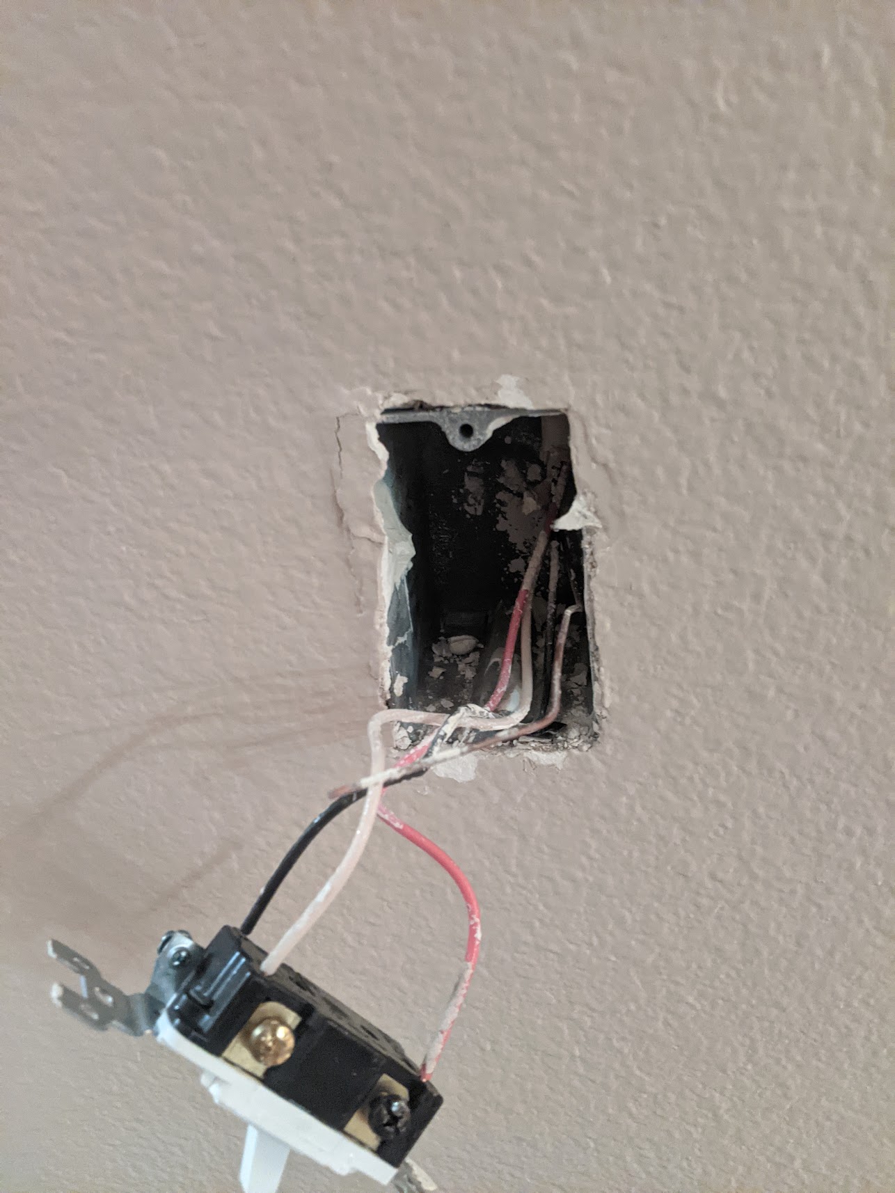
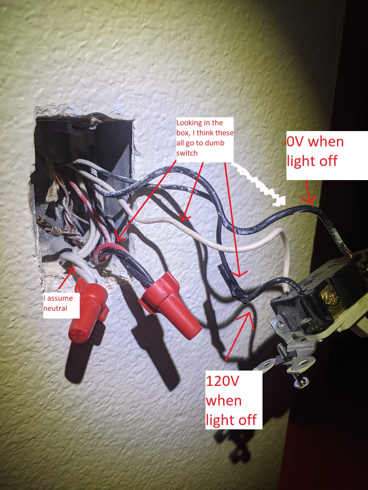
On the “dumb” side, I only have three wires, which I think are traveller, live and load. On the side I’m trying to install the red switch, I have live, load, neutral, traveller (and a mystery bunch of cables capped together (see pics).
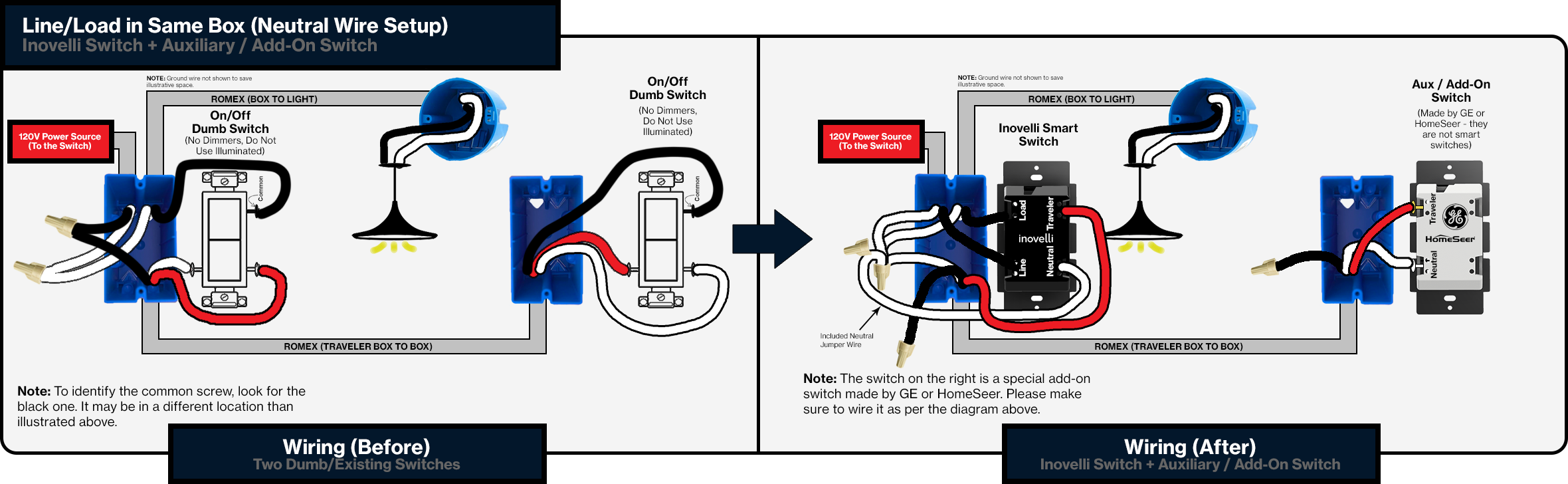
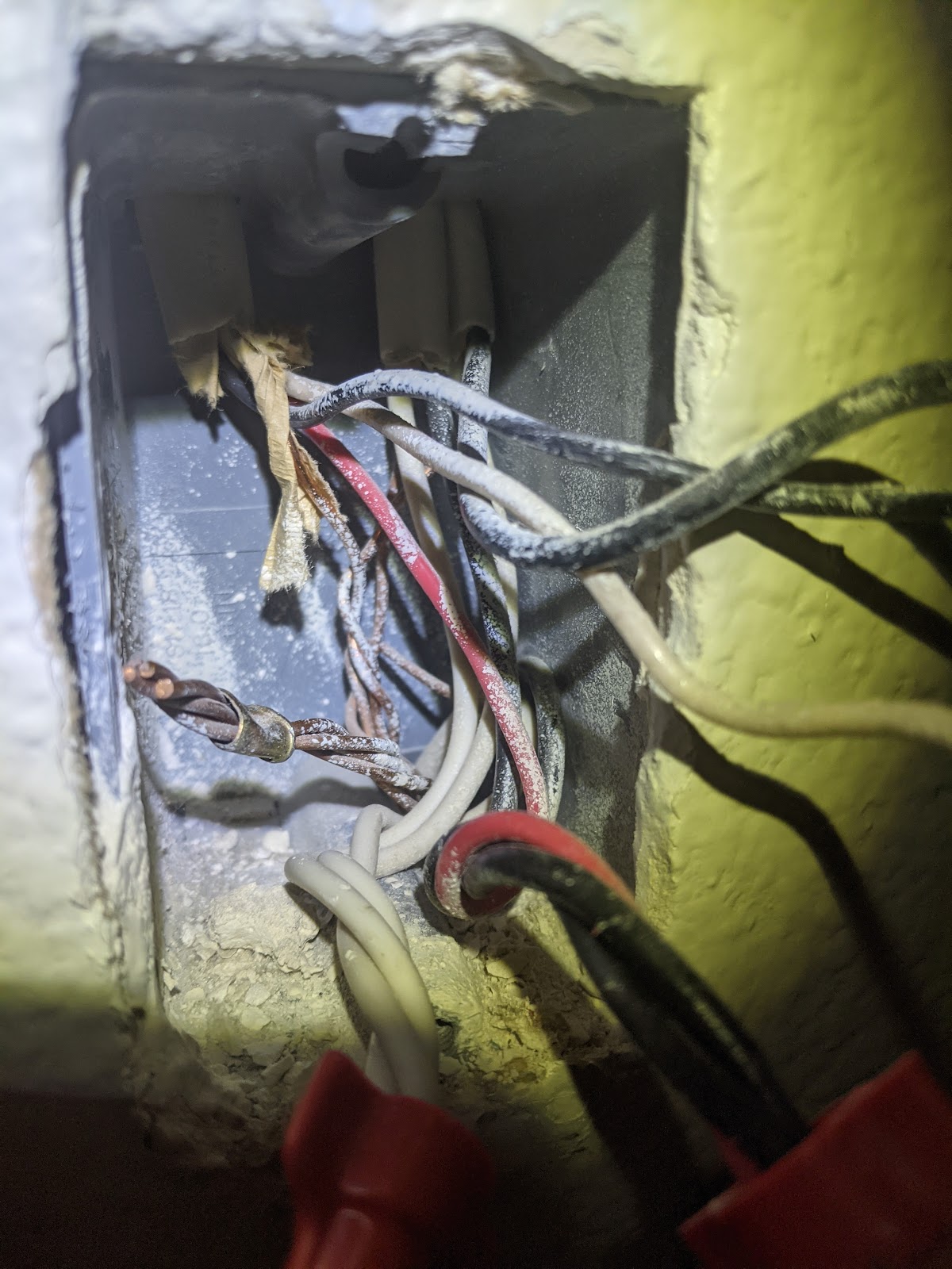
The box shown in the pictures is where your live comes in and where the power goes to the switch. I notice there is a red cable twisted with the black ones, so I assume that this is where your live connected, and that it is being fed to your other switch via the red cable in the 3-way cable.
The cable going to the lamp is one of the black ones on your switch
So I think that you have the following setup, so would need to wire this way - with the Inovelli switch in the box from the pictures:
Can you edit these pictures to label LINE (from the breaker), LOAD (to the fixture), TRAVELER (usually red between switches), and NEUTRAL (white)?
Without knowing which is line and in which box, we can’t solidly answer.
It also matters whether the fixture is in between the switches or at the end (downstream of the non-line box), but more on that later. Note if the line goes into the fixture these won’t work without a re-wire inside the fixture.
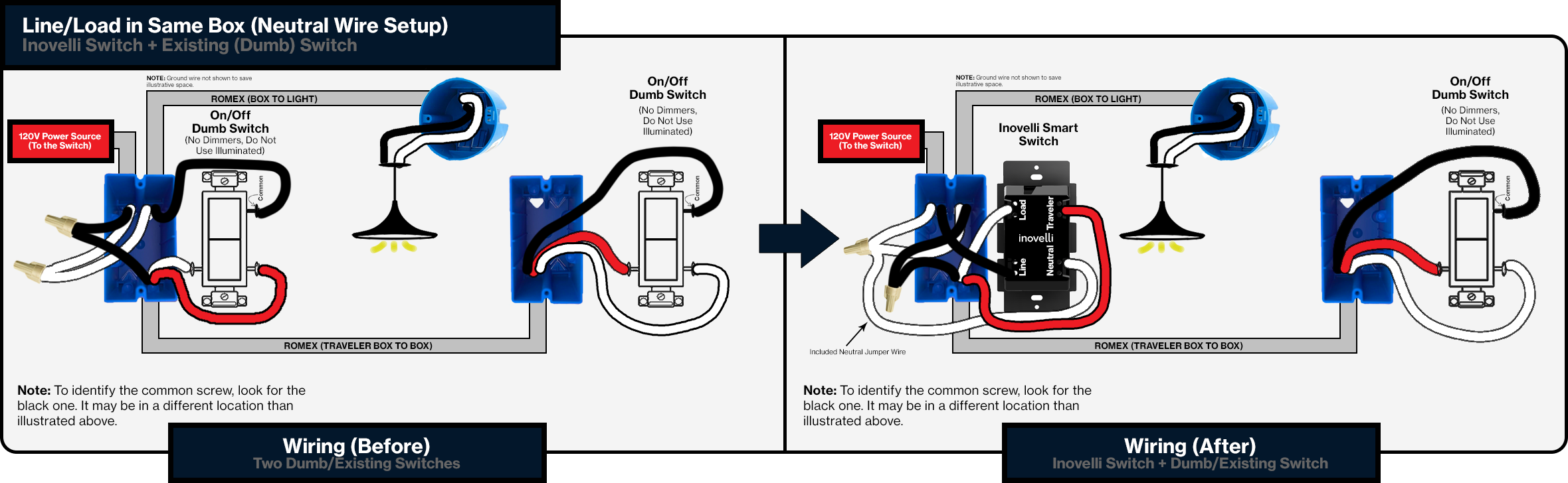
I tend to also think that box pictures is the live and load as @SViel posted. I see a red wire connected into the live bundle so I suspect that is feeding power to the other box instead of the black like the Inovelli diagram shows. But, the diagram is for a aux switch not a dumb switch so this one is possibly closer. The red and black between the switches appears to be swapped in yours compared to this diagram.
Thank you all! I’m going back to the house today, so I will take some more pictures and try to label the wires. The red wire goes into the switch on the “dumb” side, but into the bundle on the “smart” side - does that mean I should take it out of that, or use the black wire going into the existing switch instead for “traveller” on that side?
Should wire like the diagram I posted. The red is being used to send the hot to the other switch, but you have to change that so you can switch it to a traveler wire.
The black on the black screw of the switch in the smart box is the load.
(The confusing thing was there are two lights coming into the box, so I just wired them together in parallel, as they were before to this outlet. The two lights are in the top-right of the box, the power comes from the bottom-right of the box and the other switch wire is in the top-left of the box.)


 Thank you SO MUCH