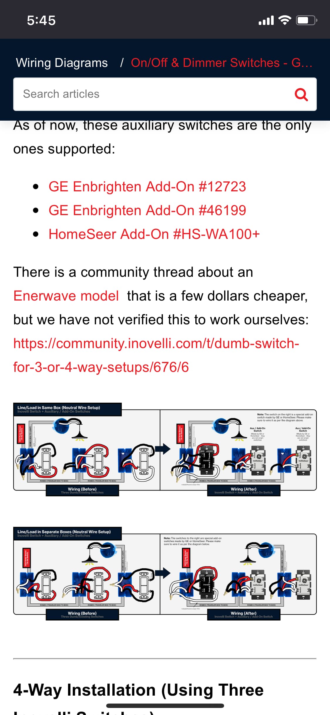
When I got to the non-neutral area it has the single and three way setups but no drawing showing my setup. I know where the line is but I don’t know for sure where the load is yet but if I can’t find a drawing showing the rest I am out of luck anyway.
Something interesting, I do have neutral wires in the line box but they are not used.
Any help is greatly appreciated. It is frustrating that there is not even a mention of this setup, let alone the missing drawing. Is this a non-standard configuration?
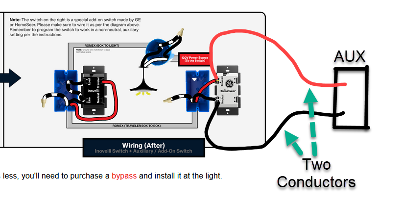
The link @harjms posted is correct, but the anchor took you to the neutral drawings. Scroll down to the bottom and look at the 3-way non-neutral. Wiring for a 4-way non-neutral is identical. Just extend to another Aux switch via 2 conductors.
“Just extend to another Aux switch via 2 conductors.” which two? Line? Load? Red or blue? When you say extend, do I need to run additional wire?
They have a drawing for every single possible configuration EXCEPT 4 way w/o neutral. Did the artist get tired and they couldn’t hire someone to do the last drawing? Can someone who understands my setup do a drawing showing the additional connectors mentioned by @Bry needed to achieve this? If you do, send my your pay pal and I’ll pay you for your time and then send it to Inovelli so that can post it there.
Killing me man… It’s me doing the drawings. There’s 4 of us here. I guess I was banking on if you understood the logic with a 3-Way, you’d be able to figure out a 4-Way, but this is a good reminder that I shouldn’t assume things.
So the first thing you need to understand is that being condescending will get you nowhere here.
The Inovelli drawings cover the typical installations with the exception of some very complicated non-neutrals which need to be evaluated individually. So no, the artist didn’t get tired.
No one here is going to look at your drawing and make any sense of it. There are typically 3 conductors between switches in a multi-way, plus at least one 2-wire in a non-neutral, at least with Romex wiring. Even with individual conductors likt THHN those conductors must be present. The one exception is if you have knob and tube wiring. If that’s the case, you need to state that.
I’m just going to say it. If you can’t figure out “it’s the same as a 3-way just extend it to the next”, you probably should not be trying to DIY install these. Remember, you’re dealing with electricity here. While the wiring may look like the drawing, you never know how the electrician that wired your house did it without testing it out. And if you don’t know how to test that, you literally could kill yourself. Spend the money you’re offering to paypal on a licensed electrician.
As for the “why” there isn’t a drawing for your specific situation, I don’t know exactly but I can only assume. There are hundreds, if not thousands of possible wiring configurations for every different situation. Exactly how many diagrams do you expect a company to provide?
@stu1811 that is correct, load and line in different boxes (on top of everything else).
And apologies to all, my frustration of working on this all day had me short and I shouldn’t convey that on here. One of those days where everything that can slow you down does, regardless that is no excuse. Especially with Inovelli, love the support I have received and was on the early buy in for the gen2 switches. Never post when you are hungry too.
I honestly didn’t mean that to be that condescending. It looked like literally the drawing list was not finished. Would have expected to see something like “if yo u have a 4 way, it is the same as the three way, just extend it” or similar but there was just nothing. But again, my apologies on sounding like a dick.
@Bry Thanks for that drawing, I would have chosen incorrect wires. So I am going to see if I can draw the rest then based on that and my line/load not in same box issue.
@MRobi “you never know how the electrician that wired your house did it without testing it out” Nailed it! So even with a totally correct drawing for “to code” wiring I may still short something out given the weirdness in my place. It looks like this third switch was almost an afterthought. I am going to triple check before I throw the breaker when the time comes.
You can’t get line and load in different boxes without a neutral on a 3 or 4 way. That’s why there is no drawing, it doesn’t exist in the field. So, no need to hack on Inovelli for something you don’t understand.
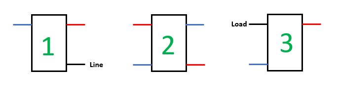
Line and load are likely both at the #3 switch in the form of a switched loop with line being fed to the #1 switch (passing through the #2 switch) via the black wire in the 3 conductor romex. Dimmer would go in the #3 box and follow the dwg by @Bry.
Electricians only use romex in 2-conductor or 3 conductor. So, there is either 2 romex at #1 (a 2 and a 3 conductor) and it has a neutral or there is a single 3 conductor romex without a neutral. If there is a single 3 conductor romex then the line power comes from the other end of that romex, ie switch #2. Then, for switch #2 if there is only 2 x 3-conductor romex then the line power comes from the other end of one of those wires, ie switch #3.
Being able to follow various wiring schemes used to sort out what was done is why you need to understand wiring with these more complex circuits instead of blindly following a wiring drawing.