I know this isnt inovelli switches but I dont know where else to go to get an answer, lol.
Im trying to replace a garage dumb outlet with a smart one. See the pictures I’ve attached. The garage outlet as 4 wires + ground going to it. 2 lines, 2 loads, 1 ground.,
The smart outlet I have only has 2 terminals, + ground.
So that’s going to be a hot and a neutral and a downstream hot and neutral. Receptacles don’t have loads unless you plug something in to them. Presuming the one black is hot, then the two blacks go to the Line holes and the two whites go to the Neutral holes.
Those two holes side by side are connected together for just what you’re doing. (So no, don’t use your diagram or you’ll pop the breaker as soon as you throw it . . ).
As @harjms alluded to, garage receptacles require protection. This can either be locally on via the breaker. If you removed a GFCI outlet, then that suggests the entire circuit isn’t protected. So if that’s the case and you want to replace the GFCI with a smart receptacle, then you’ll need an arc fault or ground fault breaker. Consult your local codes or a licensed electrician.
If your outlet that you have now is a GFCI outlet (has the test and reset buttons on it), then this wiring scheme has it providing GFCI protection to other outlets or devices. Power goes into the outlet, gets GFCI protected, then goes out to other devices.
If you wire it like you have in the picture it will work, but those downstream outlets WON’T have GFCI protection. This may be a code violation, and isn’t as safe.
The solution would be to provide GFCI protection upstream of the smart outlet- IE at the breaker. You can replace your normal circuit breaker with a GFCI breaker. Wiring that is a bit different than a normal breaker as the neutral wire has to go back into the breaker itself. You can also put a standalone GFCI unit upstream of this outlet- they make some that take a single gang box and JUST have the test and reset buttons. Or you could just install another outlet above/below/beside this one, so one outlet is the GFCI outlet, then next is the smart outlet, then next after that is the other downstream lines.
Actually, it won’t work. Well, it will work for about 6 milliseconds before the breaker trips. His picture has a hot and a neutral connecting to the same terminal.
Ooh good point, I didn’t look closely enough at that picture. You are quite right…
Was he to wire it this sort of way correctly, both blacks would go on the hot side and both whites would go on the neutral side. THAT would work but would remove GFCI protection.
Picture will help. Most outlets will have 4 wires attached if it’s not the last outlet in line.
Some electricians will tie the lines, neutral, gnd together (their own bunch) and use a pigtail to connect the switch. This way if the outlet fails, the switches downstream still work.
Or the other reason is that it’s a switched outlet.
In general, yes that will work. Code requirement is that any splice has to be accessible in a box. So, if you have 5 outlets on one circuit, typical install is to wire them in a line- circuit breaker to outlet 1, outlet 1 to outlet 2, outlet 2 to outlet 3, etc etc. That’s also why most switches and outlets have space to attach two of each wire, so if that device isn’t on the end you can use the outlet or switch itself to tie the upstream and downstream lines together.
Point is, your non-gfci outlet is much the same- one of those lines is power feed from the GFCI (or the next upstream outlet), the other one feeds power to the next downstream outlet.
More than likely, yes. Is this one in the garage too? If so, it should be protected. If you think it’s downstream of the GFCI, pop the GFCI and see if it still has power. If it loses power when you pop the GFCI, then it’s protected by it.
It has 2 Romex connected to it because there is something else downstream of it.
Well looking up the breaker, its $50. Thats already more than a smart plug will cost me. Now if I dont want to do it myself, I dont think any one is gonna come out here for less than $100. So now Im $150+ in, when I coulda spent $15 on a smart plug.
But it is still tempting to do it myself; just because lol. I will decide tomorrow when I leave for store to either buy smart plug on GFCI breaker lol.
Another possibility- just install another box or upgrade your single gang to a double gang. Keep the GFCI outlet, but put the smart outlet in the same location. So if you do a 2-gang box, you have circuit breaker - GFCI outlet - smart outlet - downstream to other outlets.
Thats an option I may do in the summer when its warmer. I’ve never switched out gang boxes. Easy? Im assuming I just cut out more drywall and swap them out. How does the gang box detach from whatever its attached to?
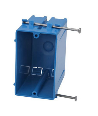
Presuming the box was put in during the original construction, most commonly, there are two nails that hold the box to the stud nailed from non-stud side of the box into the stud.
Kill the power
Remove the receptacle and tuck the Romex(s) into the box temporarily
Figure out which side of the box the stud in on
Check the other side to make sure there isn’t an obstruction preventing you from adding a bigger box
Wedge a screwdriver between the box and the stud and pry the box away. Leave the box in the cavity for the time being
Get an “old work” box that has ears on it that will cling to the inside of the drywall to hold it
Trace the cutout you’ll need to make for the new box and cut the sheet rock out
You can now easily pull the old box out. Pull out the Romex and put in new box
Tuck the new box back into the hold and secure. If you want extra rigidity, drive a sheetrock screw through the box into the stud
There is one other type of new work box where the box is mounted by nailing a flange to the front of the stud. If you have that, then use a roto tool to cut between the flange and the box, leaving the flange as-is:

 ).
).