3/4-Way Setup Challenges

Hello,

I purchased the LZW31-SN Inovelli Red Series Dimmer 8 weeks ago and am having issues getting the dimmer to work properly. I have worked with the Inovelli team to confirm the product isn’t defective.
I am using Samsung SmartThings Hub.

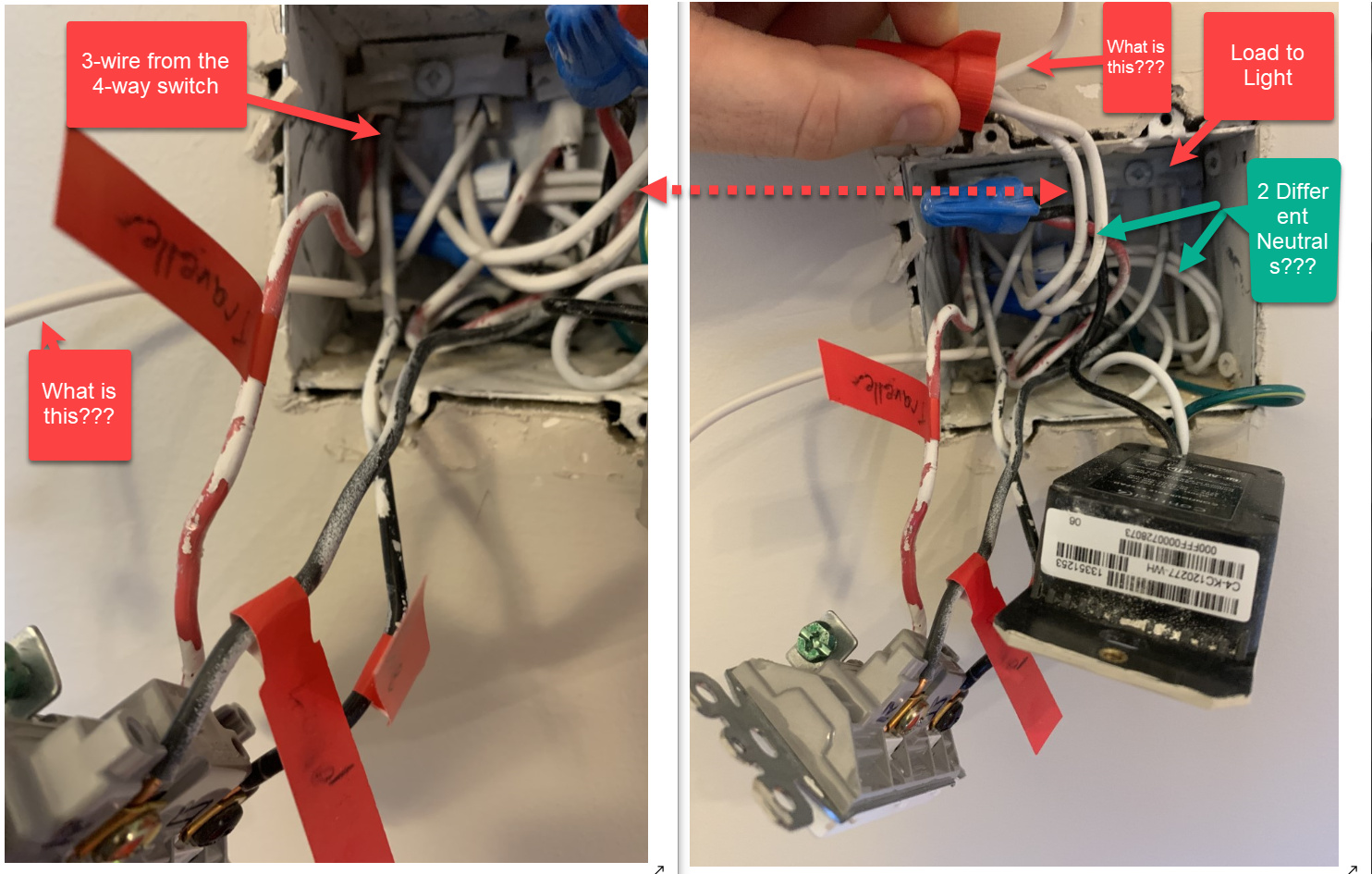
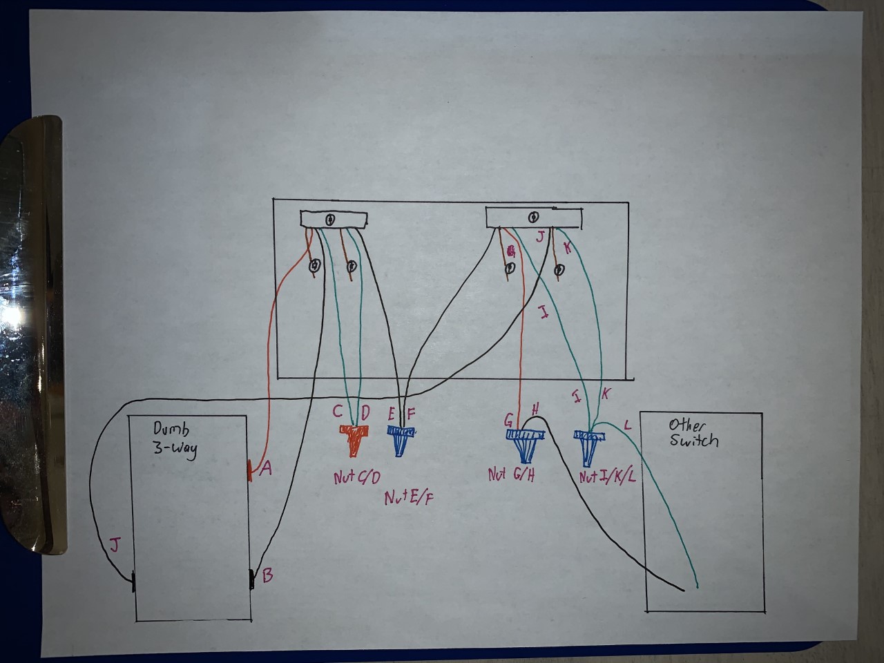
I am trying to setup the smart switch in a 4-way configuration with a neutral wire. The three switch involved are:

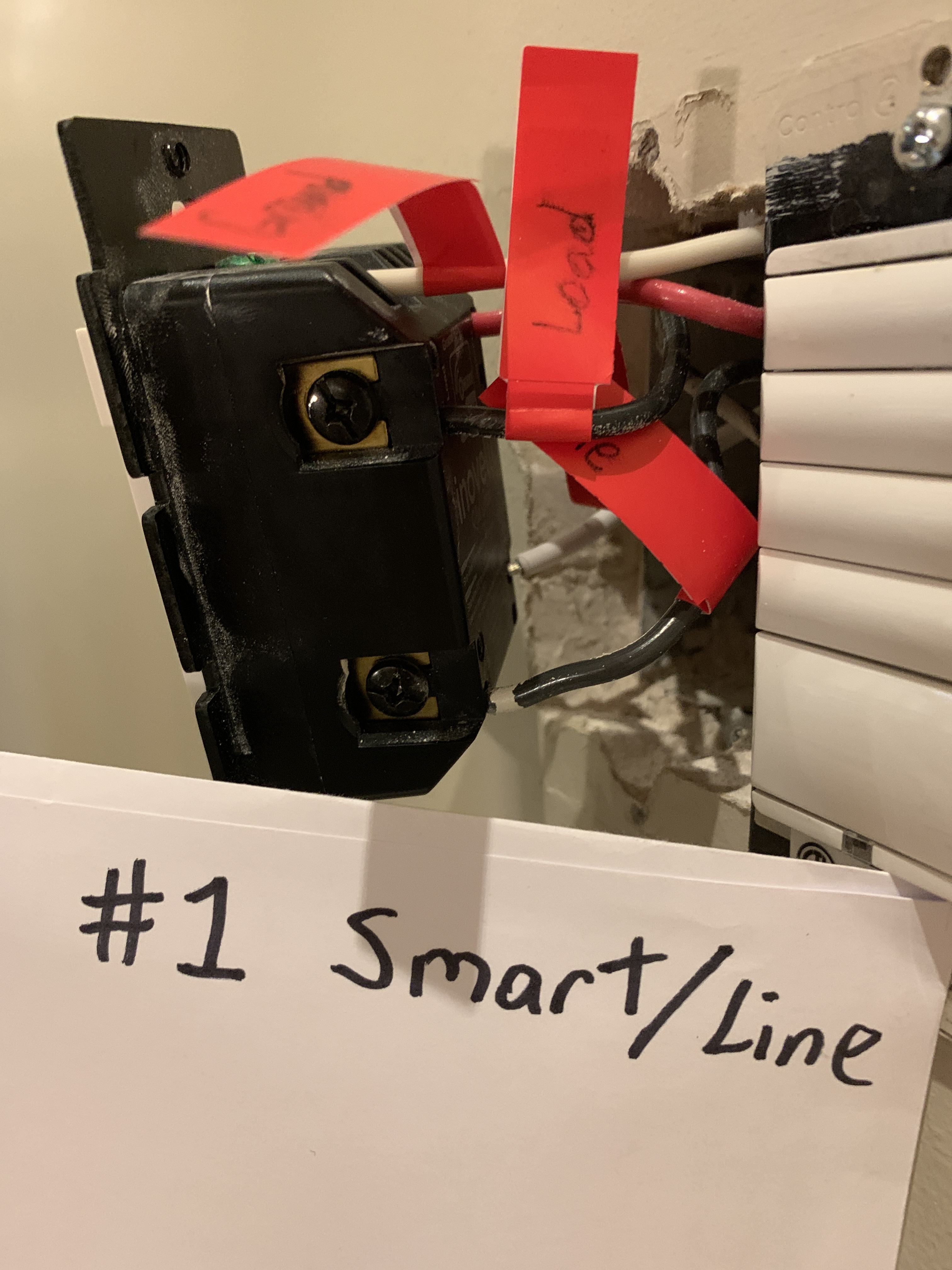
  1. Smart Switch (with line in)
  2. Dumb 4-way Switch
  3. Dumb Switch (with load)

In the current setup I get a variety of issues. Depending on the state of the dumb switches, the smart switch may or may not turn on the lights. The dumb switches, depending on the state of the other switches results in one of the 3 below outcomes:

  1. Nothing Happens
  2. Light turns on
  3. Light Blinks - the smart switch makes a loud “tick” noise then the light turns back off (most common)

I have tried a few things to date:

  1. Swapped the smart Inovelli switch out with another smart Inovelli switch to confirm the same behavior
  2. Tried 3 types of lightbulbs (including incandescent)
  3. Resetting the device
  4. Increasing min brightness level to the max (45)
  5. Trying all combinations of parameter 21/22 - Netural/No-Neutral and SwitchType
  6. I have tried item 4/5 above in both the SmartThings App AND directly through the device

I have not yet tried a firmware update - I’m not quite sure how to do that with SmartThings. I have also not yet confirmed the wiring is perfect.

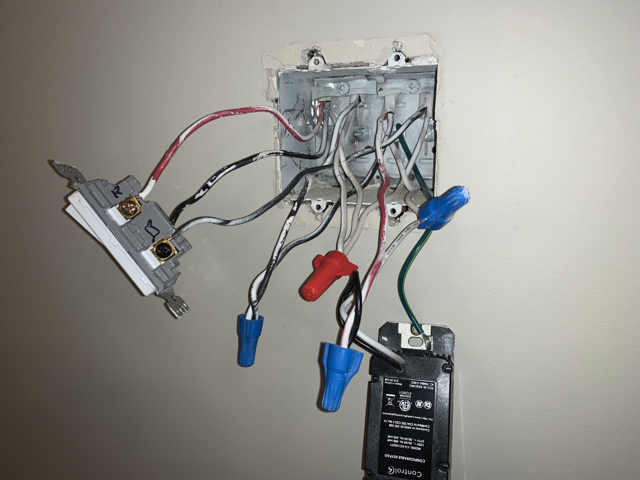
I took a variety of pictures per below, I was hoping to send a video to better show each wire, but hopefully this can do the trick instead.
Sorry if any aren’t clear enough - happy to retake any as required.
I took 3 pictures of each, but unfortunately as a new user I’m limited to only sharing 5.

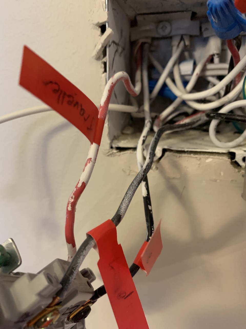
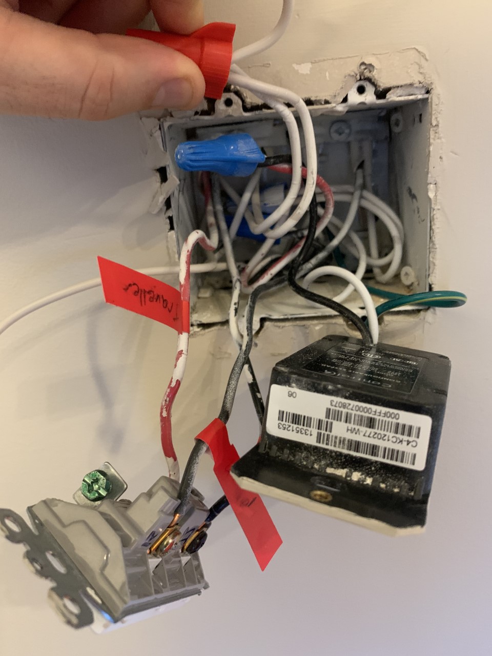
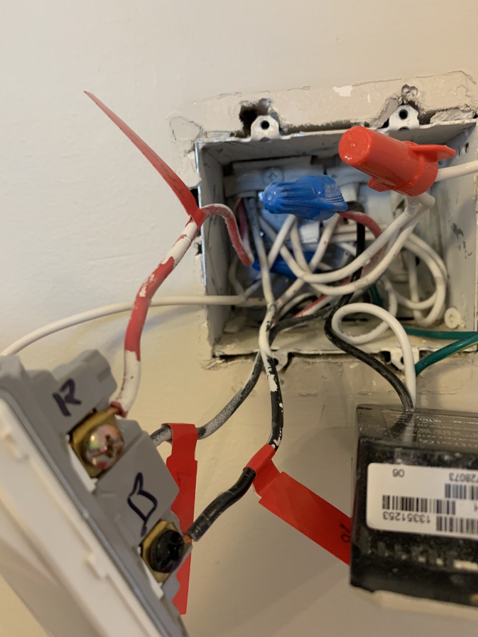
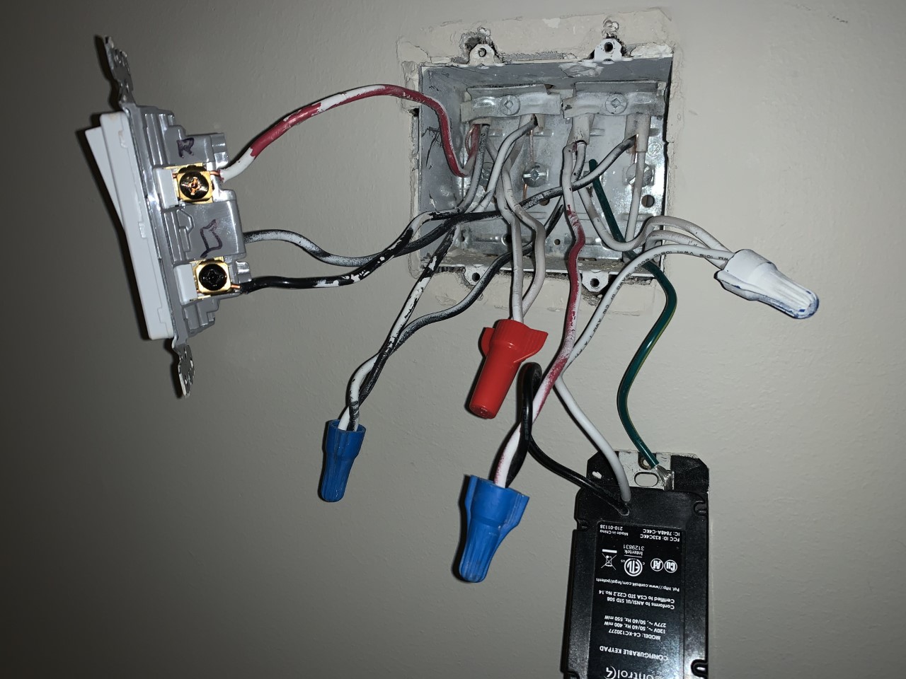
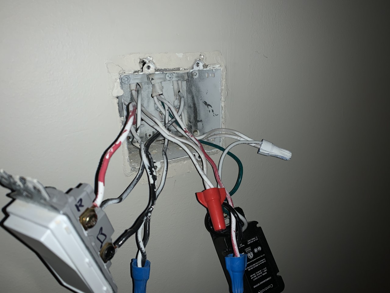
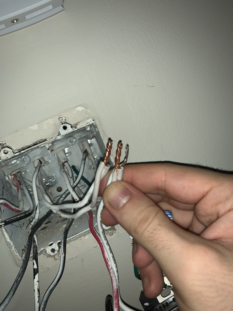
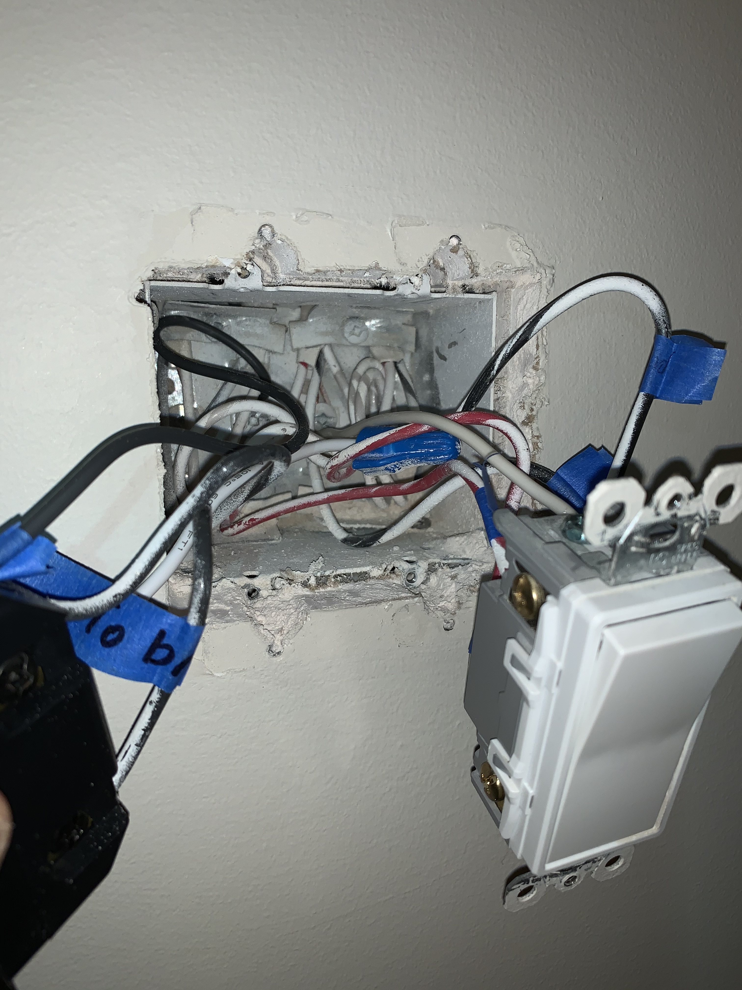
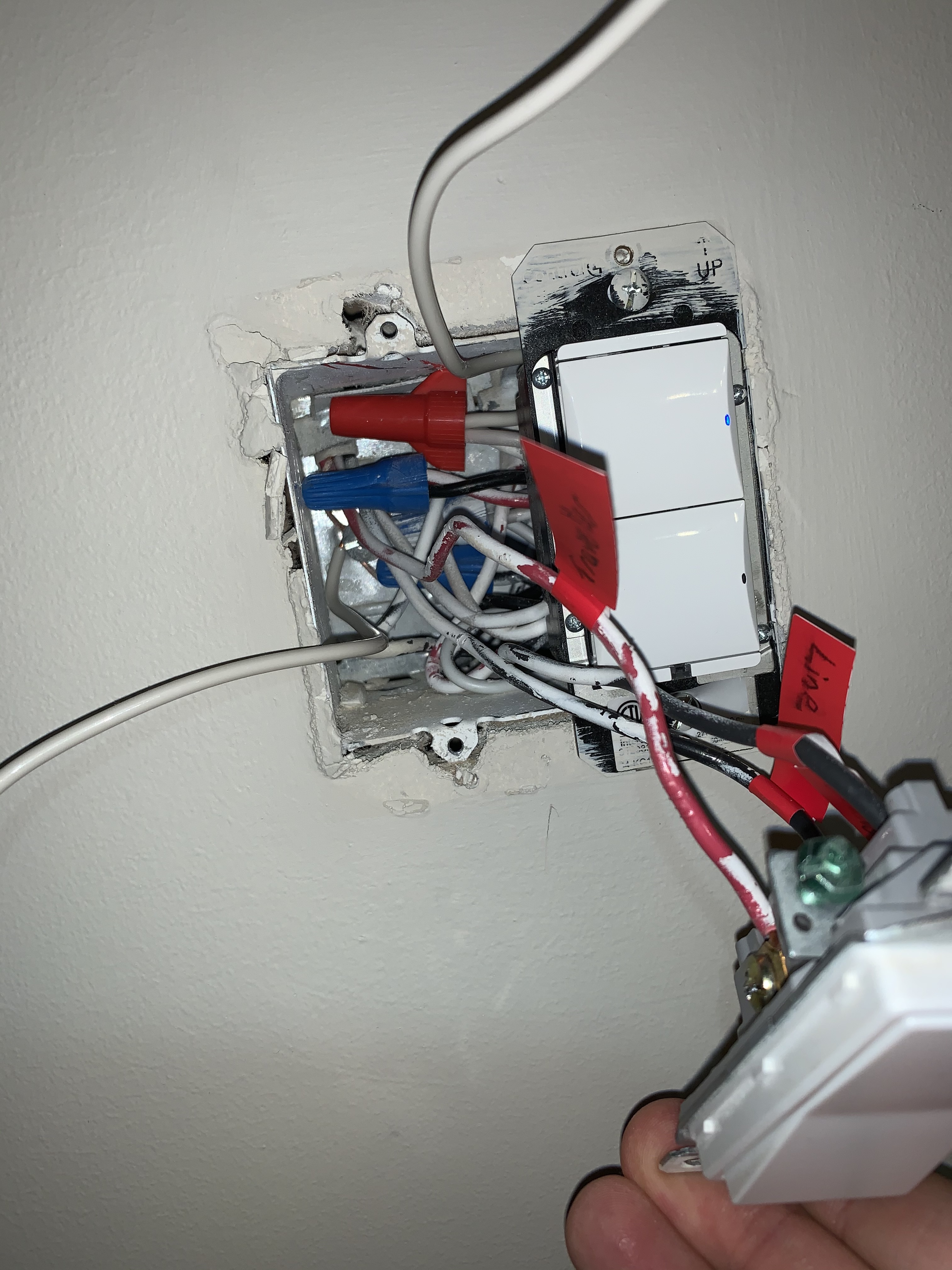
Pictures - Smart Dimmer (Line in)
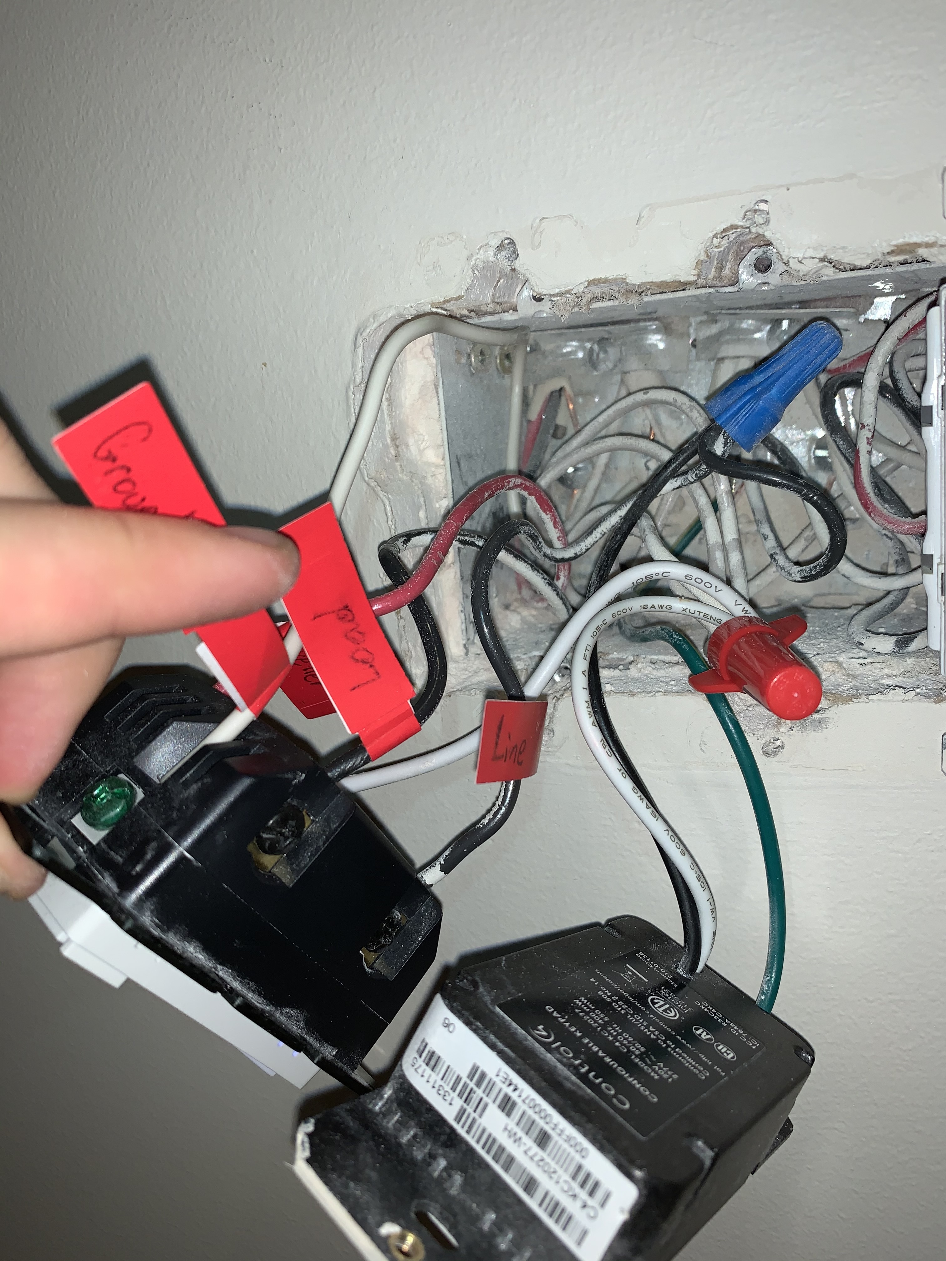


Pictures - 4Way

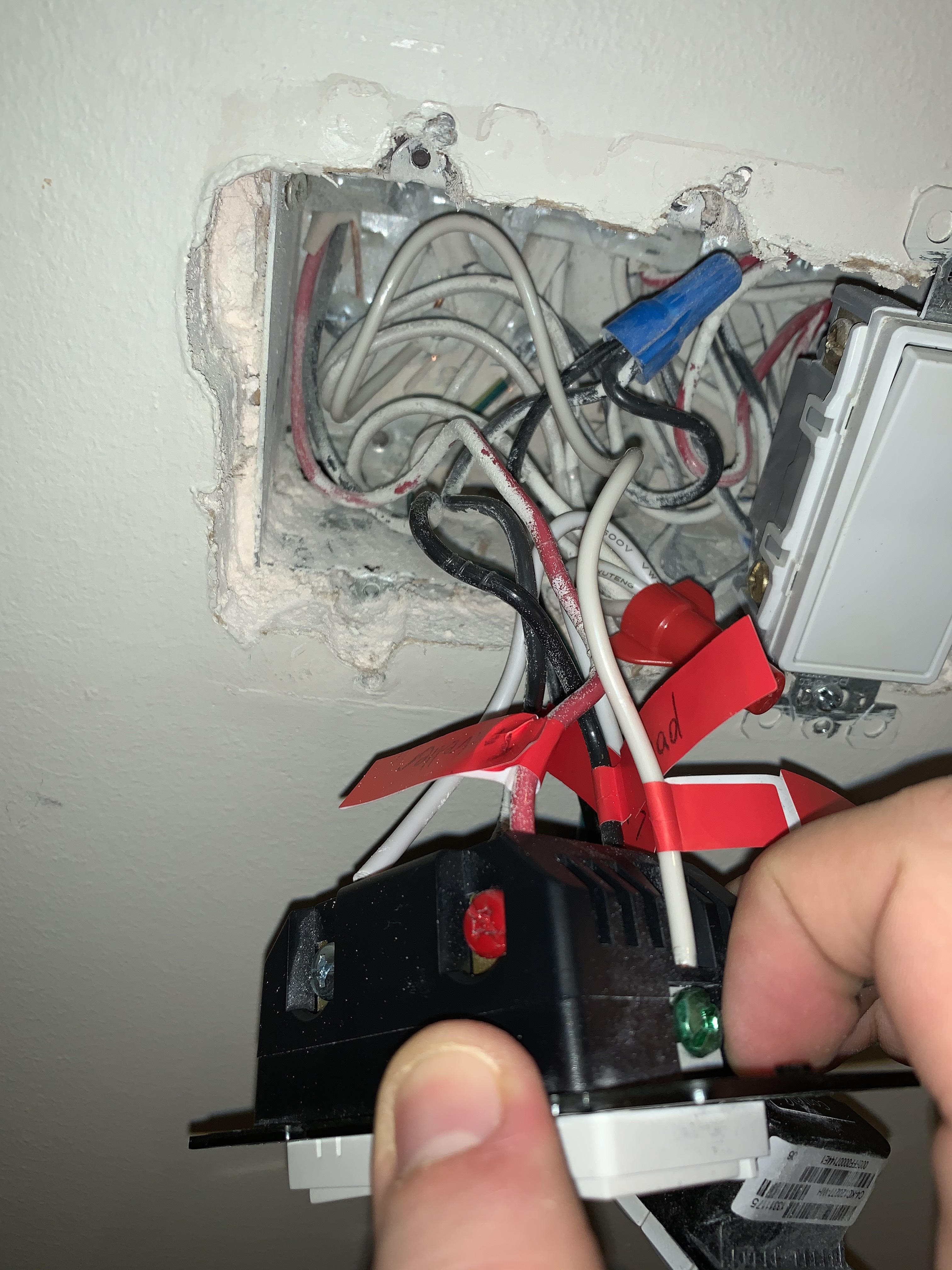
Pictures - Dumb Switch (Load)

Thanks for any help that can be provided! I would love to get this switch going!
Let me know if you would like any additional pictures taken - sorry I was only able to attach 5.

Happy holidays.

Greig H.

So when you started working on this, did you change any of the wiring of either the 4-way switch or the far box (not where you put the Inovelli)? In other words, is the only work you did in the Inovelli box?

I can’t see enough of the far box with the 3-way dumb switch. I THINK you have a Line in the Inovelli box and the Load in the far box. By “far” box I mean the 3-way dumb switch box where you are NOT putting the Inovelli.

For some reason, you have a conductor labeled LINE in the far box. This may just be a terminology mis-use, but there is no Line in the far box, or at least there shouldn’t be. Why did you label it that way?

In the far 3-way box, if your Load is here, then you should have the 3-wire from the 4-way switch and a 2-wire going to the light. The red and black travelers from the 3-wire should be on the two brass screws with the white bundled with the other neutrals. For the 2-wire going to the light, the black should go to the BLACK screw on the switch and the white bundled with the neutrals.

I can’t see those connections, but if the black screw is on the bottom, the Load conductor and the traveler may be reversed.

If you can, post more pictures of the far switch. Pull out as much as possible and move the wire nut out of the way.

1 Like

Good morning Bry,
Thanks so much for the quick response.

No, when I started on this, I labelled everything from the old wiring setup and tried to keep it the exact same (only adding neutral wires). I tried the Inovelli at a few locations until I learned it should be at the main line in.

Yes, you’re probably right, it is likely just terminology mis-use, I likely just wrote that down due to colour and that it was bring power in, but technically I guess I should just refer to that as another “traveler” right?

In the far, dumb, 3-way box where the load is, I have 3 wires leaving the back of the switch per below.
The red wire is going to the top left of the box along with the incorrectly labelled “line” wire (bottom right on switch) - see first picture below. The top right wire labelled as “load” is going to the top right of the box - see second picture below.


Yes the black screw is at the bottom, going to the top left of the box.

Do these new pictures help?

Thanks again for the help, I really appreciate it.

Greig H

Referring to the far box with the 3-way switch, are you ABSOLUTELY SURE it was wired like that an it was working? Is there any possibility the conductors were removed from the switch and put back?

Also, was there any other re-wiring done in that box? For example, did you add that red wire nut or was it there previously?

I see a couple things but would like your answers to take it a step at a time.

I’m asking this because you said that you tried the Inovelli in a couple places, which suggests to me that you may not have put the wiring back correctly.

Do you have pictures from before you started?

I took some light notes before I started and it appears I flipped the one black and the red, I just put them back to how they were before, but with no change to the behavior (image below).

No, I’m not absolutely sure I wired it the exact same way sorry. However, I do know it was working properly before.

The only change I made was adding the white wire/red wire nut as you noted - this was when I had, an one point, the Inovelli smart switch here.

No sorry, no pictures before, just the marks I had written on the switch before I had removed the wires (I wrote R in sharpie where the red was). I also noted B=BLACK and BW=BlackWhite, but looking back, those aren’t very helpful as both wires have some black/white on them.

The problem is that I’m afraid you’ve modified wiring in the far box and haven’t put it back together correctly. There are things I see presently that concern me, so there is a bigger issue that just getting the switch installed. If you re-wired a dumb switch where the Inovelli is right now, I’m pretty sure it still wouldn’t work. Of course, there is always the possibility that I’m missing something.

Look at my drawing for details:

1 - You have 2 neutral bundles in the box, one with the red nut and one with the blue. You technically can have 2 neutral bundles in a box if there are different circuits, but in your case the neutral from your 3-wire isn’t even connected to the neutral going to the light! Were all the whites bundled together before you starting tinkering?

2- What is that white going off screen at the top. Is that on old loose pigtail that shouldn’t be there?

3 - What is that white conductor going off screen to the left? That probably should not be an unterminated conductor.

Understand that I’m not going to suggest how to fix your wiring, but I’ll point out what doesn’t look correct to me. If you were starting with a pristine, working environment, then things would be easier. But when a number of incorrect changes have been made then I’m disinclined to go further and suggest you consult with an electrician to get things put back properly.

OTOH, if you can explain what I’m asking about, maybe there is a logical explanation.

All I know for sure at this point is I’m pretty sure you added that red nut, as your electrician used blue and it looks newer. If you added it and supposed put things back the way they were when you started, then that definitely doesn’t belong there.

Hi Bry, thanks again for the response. This house is currently wired with Control4 switches that I’m hoping to move away from, the one blue nut seems to just be extending a wire going to the Control4 switch.

I have removed the two wires you noted where you flagged “What is this???” I added these when the Inovelli switch was here. One was a ground and one was neutral.

I only added the red nut to allow my additional wire to be added in, now that i’ve remove that wire (it’s not required anymore) it’s back to its original state.

I have pulled the wires out further to better illustrate the situation.
I have also drawn a picture in case any wires are hidden through the 3 other pictures, I also added some labels so we can refer to them easier.

Nut C/D is now exactly as it was before - I’m 100% confident in this (The thicker wires are very tightly and neatly woven together - I wouldn’t have been able to do this)

Please see below:

Thanks!


Ok thanks. Looks cleaner and easier to see. But same question as before. The 3-wire coming from the 4-way switch is at the top left. That white conductor should be the neutral which is sent along via a daisey-chain from the Inovelli box. The load to the light is the top right 2-wire, right (it’s attached to the switch). Why is the neutral in the inbound 3-wire only attached to the top 2nd from left 2-wire and not bundled with the neutrals that include the one to your light? (If you know.) The 2 separate neutrals in the box still does not look correct to me.

I’m referring to C & D in your diagram. Since they should be a neutral, why aren’t they bundled with J, K & L? In your post you advised that you added the red nut and that it’s not needed any more but it’s still in the picture?

Also, I believe you have the two blacks reversed on the 3-way switch. The black common terminal should go to the 2-wire to the light, which it isn’t presently.

Thanks for the response.

Nut C/D had a nut on it that was too small for a third wire, so I used the red nut to allow me to add a third wire. I have since removed that wire, but left the nut.

The wires are all very thick, maybe that’s why C,D, I, K and L aren’t grouped?

Thanks, I’ll flip the black wires.

Ok thanks. Out of curiosity, referring to the far box, is the light you’re working on and the light the other Control 4 switch is controlling on the same circuit breaker?

Nope - different breakers…hmmm… odd…

I took a picture of the thicker cords - maybe thats why the electrician who Installed the Control4 didn’t combine all wires…maybe?

No, if they are on different breakers (at least in US) they must be separate. Not sure about Canadian electrical code, but in the US you can have multiple circuits in a box but the neutrals must be separate. Probably the same in Canada as bundling different-circuit neutrals together will wreak havoc on arc fault breakers.

The problem as you might suspect, is that as wired, your load is using a neutral belonging to a separate circuit than the one that is powering it. That white from the Load ought to be bundled with the neutral from your 3-wire and that other 2-wire.

Thanks, I have made that change. It seems to be working better, but still not correctly.
e.g. Results of flicking switch 10 times:

  1. Switch on - Smart switch “ticks”, smart switch indicator lights up and ceiling light turns on
  2. Switch off - Smart switch indicator light turns off and ceiling light turns off
  3. Switch on - Smart switch does not tick, smart switch indicator lights up and ceiling light turns on
  4. Switch off - Smart switch indicator light turns off and ceiling light turns off
  5. Switch on - Smart switch does not tick, smart switch indicator lights up and ceiling light turns on
  6. Switch off - Smart switch indicator light turns off and ceiling light turns off
  7. Switch on - Smart switch "ticks, smart switch indicator lights up, then off and ceiling light turns on **then off (**very quick, more of a blink).

Perhaps I’ll do a hard reset, change switch type parameter, neutral parameter, and min-dim parameter and see if just resetting all those items again helps.

Not a bad idea.

With a dimmer, you should hear a single click with each up or down press.

I would use an incandescent bulb(s) while you’re working out the kinks.

Thanks, I just reset everything and put in incandescent bulbs.

  • Min Dim=45
  • Dimming Speed = 0 (Instant)
  • AC Power Type = Neutral
  • Switch Type = 3-Way Toggle

Still getting the same behavior.

Can you please post the far box like the last set but with the changes you made? Thx.

Absolutely - please see below for two pictures with the changes:

  1. Black wires were corrected to have the black screw go to the load
  2. Neutral (wire k) moved from I/K/L nut to the C/D nut (red nut)

Thanks. That side looks fine now.

I read above, but the bad behavior is the switch doesn’t always click and after a number of “on” presses, the light turns on then off quickly?

Try cutting max dim to 80%.

Tagging @harjms the 3-way weird stuff happening expert.

What firmware are you on? You can find it in the IDE in the device details page. (“Ver” in Raw Description)

Thanks, I have changed the max dim to 80%

From the 3-way we’ve been working on, several outcomes occur when I flick the switch:

  1. State is changed (from on to off, or off to on) without a tick - by far the most common, I just tested this and it worked 30x in a row.
  2. There is a tick when the light should be going on, it blinks on, then quickly turns off
  3. Nothing occurs (only from off state to off state)
  4. From off state, smart dimmer ticks, then light turns on as expected

From the 4-way, if the 3-way is on, things are a bit different - The Inovelli smart switch now ticks everytime, and the light usually goes on, or blinks, then stays on (on --> off --> on)

Again from the 4-way, if the 3-way is off, things are again a bit odd. Similar to before, the Inovelli smart switch ticks every time. If I go slow, the light blinks on, then turns off. The next toggle then does nothing (still clicks) then again on the subsequent toggle, the light blinks on then turns off. This pattern is consistent if I toggle the buttons slowly…if i quickly press the button up and down, then the switch starts working as expected (no blinking) for a short period, on and off, turns the lights on and off (no ticking). Until eventually the lights don’t turn back on, in which case i just have to toggle back and fourth a few times to repeat one of the two types of cycles mentioned.

From the main inovelli switch, there is another set of behaviour.
If the 3way is off and the 4way is on - then the inovelli, can’t turn on the light (the indicator goes on and off and there is no tick.

If the 3way is on and the 4way is on - then the inovelli, can’t turn on the light (the indicator goes on and off and there is no tick.

If the 3 way is off and the 4way is off - then the inovelli ticks and works as expected

if the 3 way is on and the 4way is off - then the inovelli ticks and works as expected

Sorry - i know that’s alot, hopefully it helps.

Regarding the version, I’m on 1.47

Raw Description:
“zw:Ls2a type:1101 mfr:031E prod:0001 model:0001 ver:1.47 zwv:6.04 lib:03 cc:5E,6C,55,98,9F,22 sec:26,70,85,59,86,32,72,5A,5B,73,75,7A”