The switch/dimmer has to be at the LINE junction/box in case of a 3-way or 4-way. This is needed to make sure power is always available to it. If you don’t it will lose power and your setup will not function correctly.
I am trying to install a LZW30 in a 3way setup. I am pretty sure I installed it in the line box, but when I turn off the dumb switch, the LZW30 just clicks when any button is pressed and light doesn’t come on. It doesn’t lose power or anything however when the dumb switch is off
Does the below guide apply to the LZW30 as well? Does it need to programmed manually to work on a 3way setup? @Eric_Inovelli
@mraz.camren - You need to configure your switch parameters 21 and 22 for Neutral/Non Neutral and 3-way toggle (for dumb switches).
Thank you. Can it be done via the config button itself?
@mraz.camren - Yes. You definitely can set this up via the config button. Look for the configuration table in the manual to make the change.
Thank you! I will try out your suggestions
That’s something I am confused about. The manual seems to be for the dimmer. I have the Black series On/Off switch, and wondering if the same config table will apply
@mraz.camren - I’m an idiot. I didn’t catch the 30 vs. 31. So, yea there’s a thing with some of the loads that prevent the switch from automatically selecting/finding the switch in a a load only or 3 way setup. The above manual does not apply; either replace the bulbs with incandescent ones (changes the load characteristics) or upgrade to the latest beta firmware. That firmware will allow you to force it to a 3 way setup.
Oh interesting. Thanks again for the info!
If possible, change to incandescent bulbs (briefly), pull air-gap switch or turn off -> on circuit breaker. Then try the dumb switches. It ‘should’ recognize the new load and switches.
Firmware 1.17 added the parameter 13. "Enhancements
Add parameter 13, for some special load types. Can be used in certain 3-way dumb switch setups where the load is confusing the switch as to which state it should be in.
Parameter 13
Size: 1 Byte
Default: 0
Range: 0-1
0: Detect Load Type.
1: Manually set for special load type."
Recommend going with 1.19 if you chose to upgrade the firmware.
Ok, updated the firmware, set the parameter for the special load type and things are still not right. The light keeps turning on and off. And sometimes the up/down button won’t even do anything. I also set the switch to neutral+dumb via the config button, and nada. So I am at a loss right now. Someone help please
You don’t sound as if you are oozing with confidence about your wiring. If you like, we can take a look.
Post pics of both switches. Pull the switches and all of the connections out of the box so we can see what’s going on. We need to to see the connections to the switches AND clearly inside of the box so we can see what wires are coming into the box.
Do you have any “before” pics with the old dumb switches in place? If so, post those first.
Here are some pictures
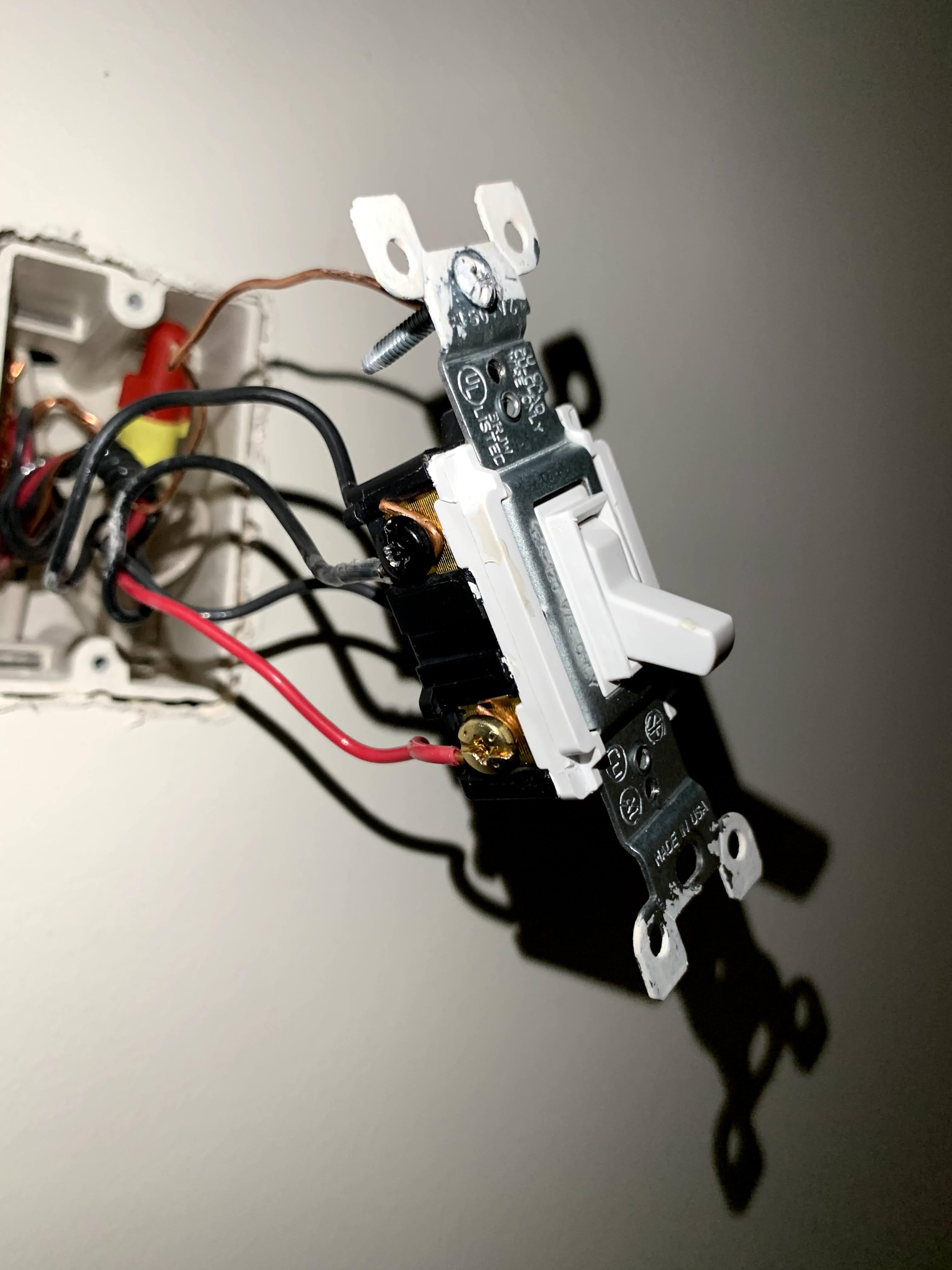
Old switch
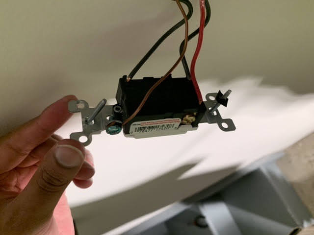
Other dumb switch
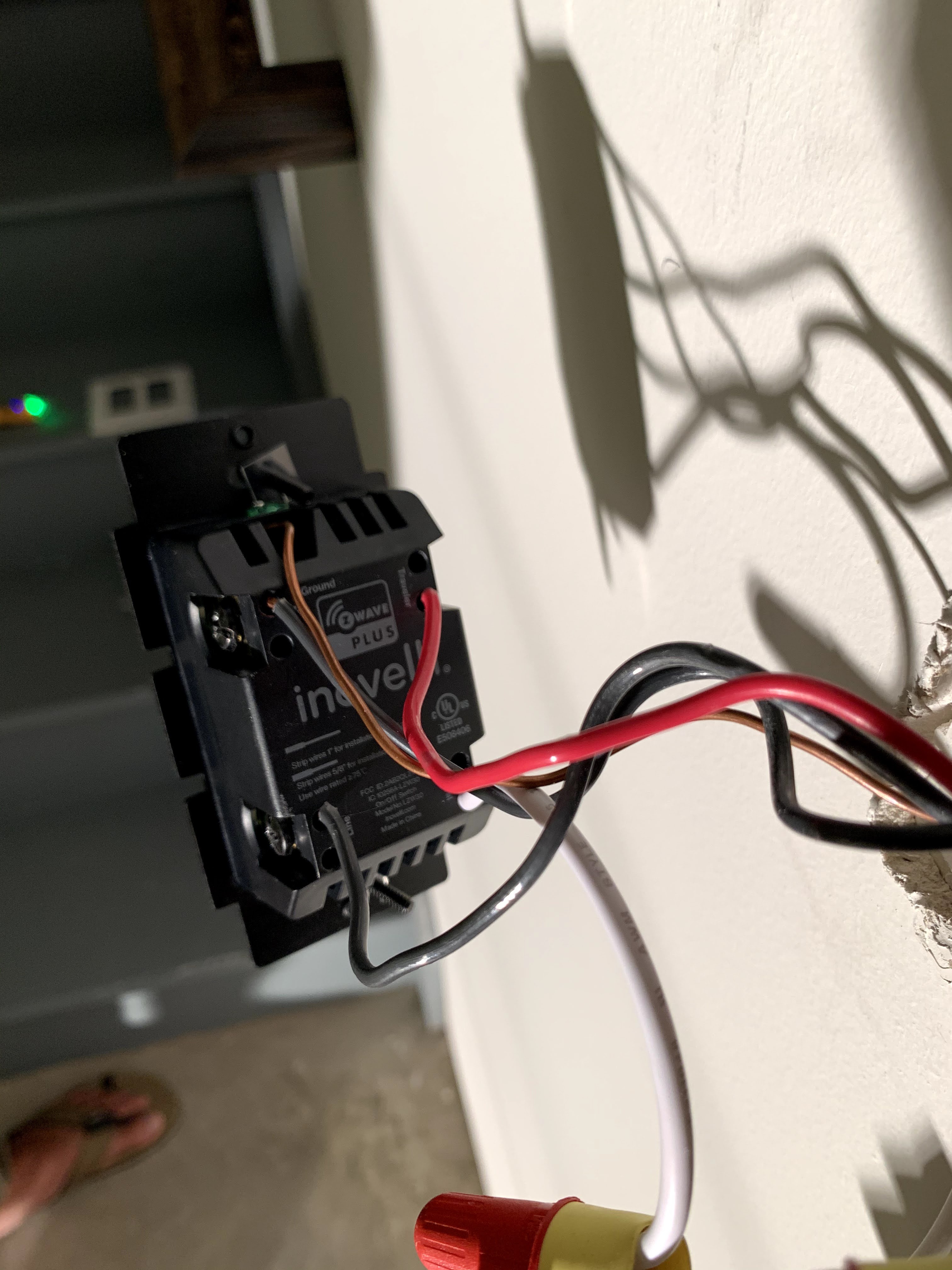
LZW30
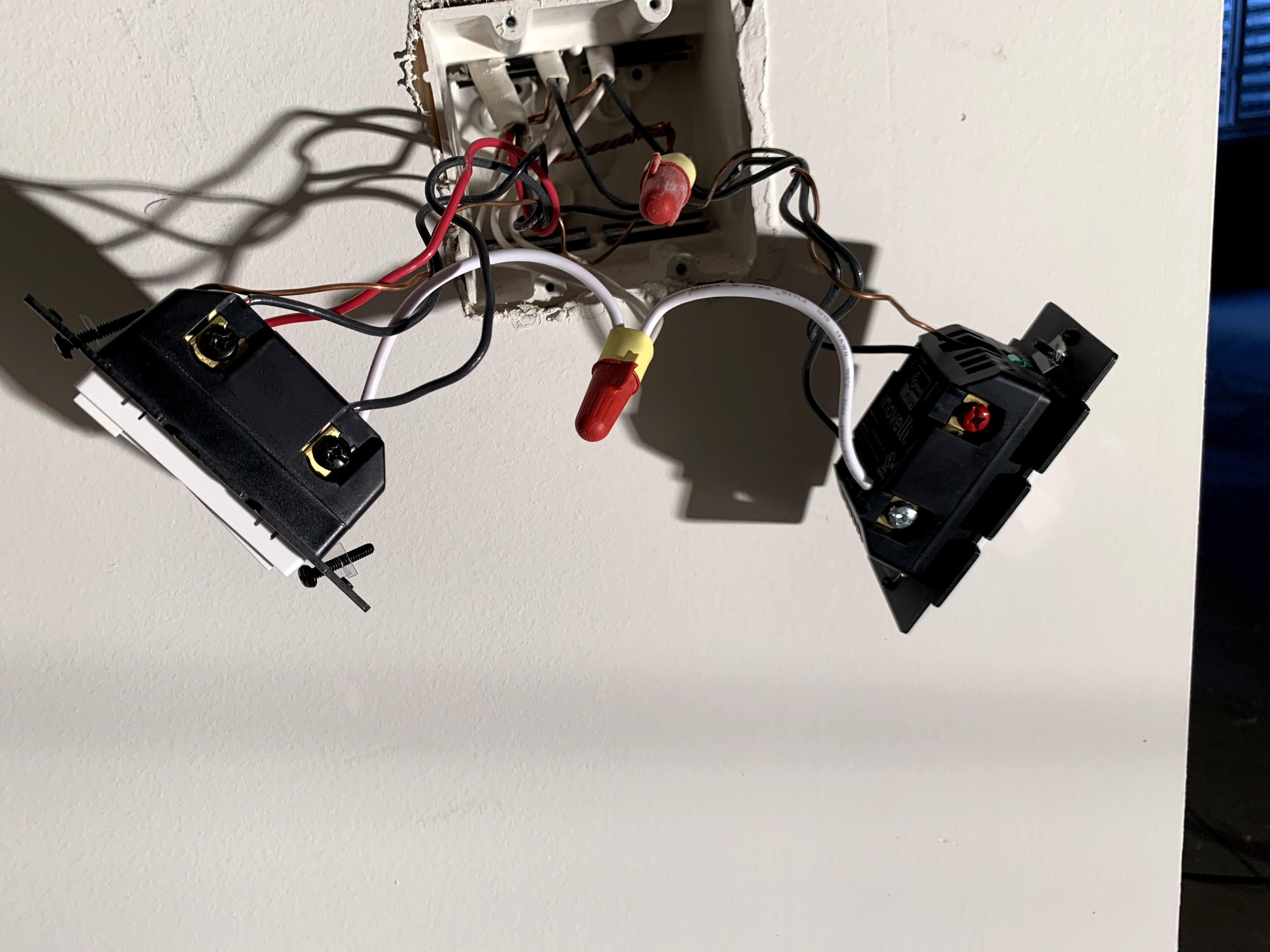
Box
The switch on the left is of concern here. The LZW30 on the right is a single pole and is working just fine. I am moderately sure of the wiring because I had also tried to install the LZW30 on the other box, but every time I turned off the dumb switch, the LZW30 would completely lose power, so I swapped boxes
Appreciate any help/advice that you can provide
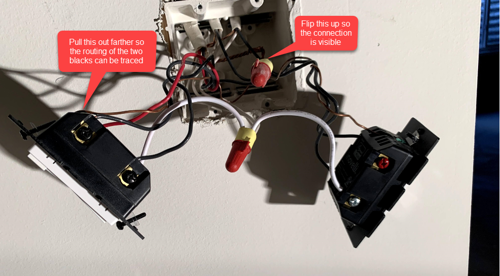
You’re going to have to do better with the pictures. I need the left Inovelli in the double box pulled out so I can trace the blacks. I can’t see where the LINE and the LOAD blacks are going. Also, flip that wire nut up so I can see what’s connected. I’m guessing that you think this is hot feed but without seeing what’s connected there it’s hard to tell.
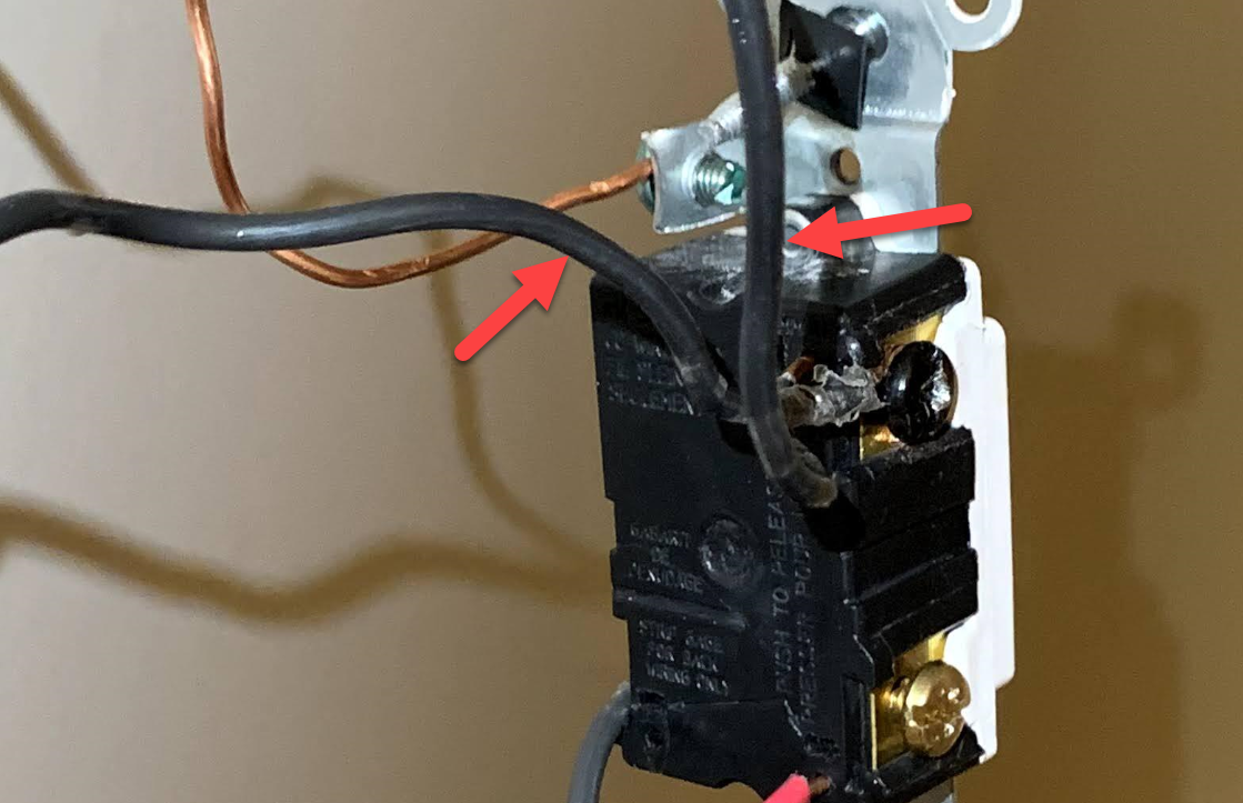
In the single box, I can’t see into the box. I need a picture that is in focus on the box. Also, are there 2 conductors connected to the one black screw that is visible?

I messaged you some pictures. Appreciate your help
@Bry
So without testing it does appear that the double box has the constant feed. I’m basing that on the fact that the center 2-wire also feeds the switch on the right which is not part of the equation but is working fine.
Same question as before. In the single box with the dumb switch, why are there 2 black conductors connected to the black terminal? It may not be incorrect, but raises suspicion as I would expect to only see one conductor there. What do these switches switch? A single light, multiple lights? What type of light(s)?
There are two light bulbs controlled by these switches. I had tested just unplugging one of these black wires, then one of the light bulbs wouldn’t come on
The bulbs are Satco LED bulbs
The wiring looks correct and the 2 conductors on the dumb switch should be ok given your explanation.
So the Inovelli appears to power up ok, it’s just that with the dumb switch toggled in one position the Inovelli doesn’t do anything. Is that a fair description?
When you throw the dumb switch, does the Inovelli appear to shut off at any point?
Did you try temporarily swapping for an incandescent as @harjms suggested? Sometimes LED bulbs have weird effects with these switches.