I’m trying to wire a 3-way switch using a White series dimmer + aux switch, but my circuit doesn’t match any of the diagrams. It doesn’t match the “Neutral wire” diagrams because the line comes into the box without the neutral (I don’t have line and neutral in the same box anywhere). It doesn’t match the “non-neutral” because (basically) the layout is MAIN → switches → light and not MAIN → light → switches.
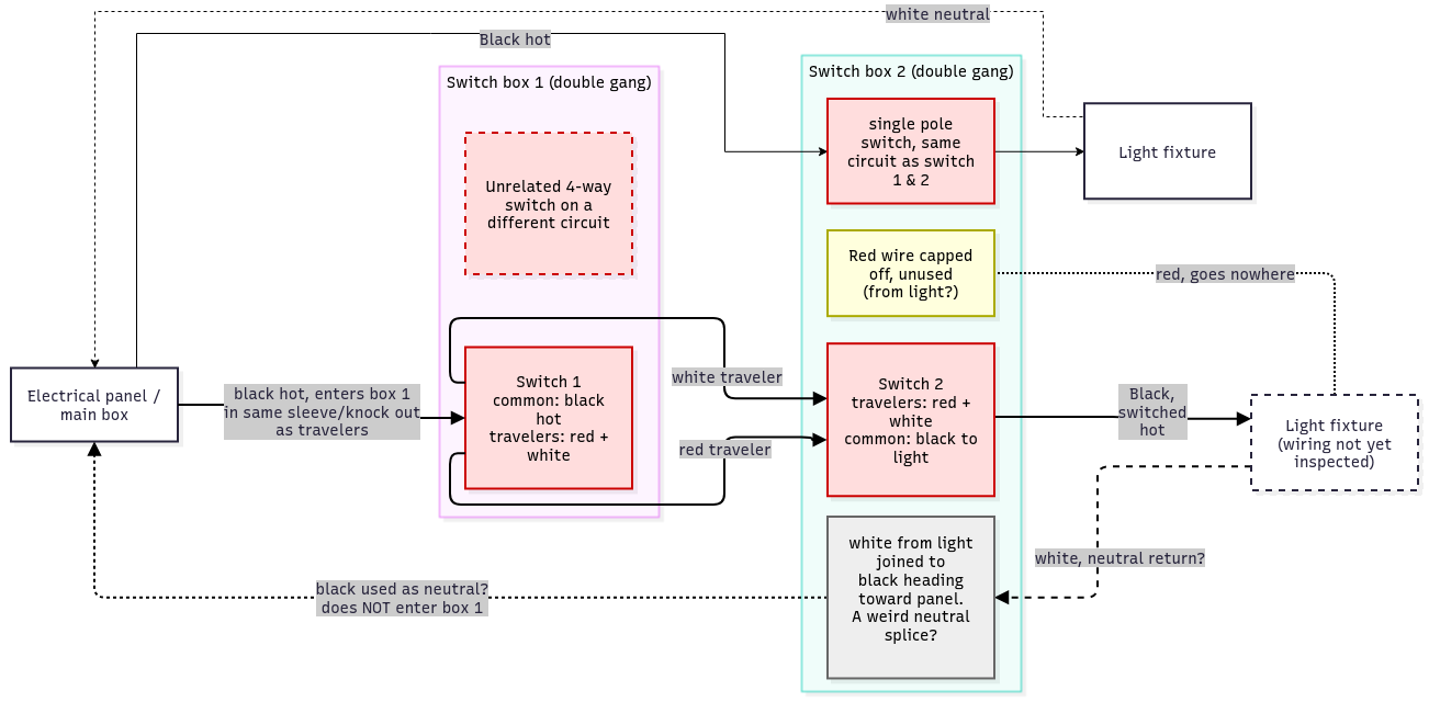
Here is a diagram of what I’m looking at. Dotted lines are guesses / not directly measured or observed.
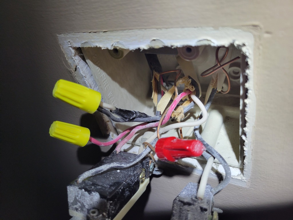
Here is a photo of “switch box 2”. The one on the left is the one controlling the light I’m working on. Eventually I want the other single pole switch (controlling another light) to also be smart (using a white series dimmer).
Sorry, I can only embed two images so I figured these were most useful. I have pics of box 1 if needed.
I don’t have a bypass, but I’d be willing to buy one if needed. I planned to use a smart dimmer + aux switch, but I do have a spare smart dimmer so I could use two of those with no aux if that made sense.
Based on the photo alone, it appears you have a switch loop. Power comes in on the white wire with black tape (from the leftmost cable), goes through the connected black wire to the other box as the Line/common wire (through the middle cable), comes back from the other switch over one of the travelers (red and white, also in the middle cable), then goes back to the light on the black wire (from the leftmost cable).
I assume that the additional red wire (from the leftmost cable) is for use a potential ceiling fan, but I could be wrong.
So, again based on the photo alone, you do not have a neutral in that box. Even the right switch is a switch loop… and that ground wire should be tied to the other ground wires.
The white wire with black tape is your Line, and the black wire from that same cable is your Load. You will want to install the main dimmer in this box using those two wires, adding a pigtail to the black and white wires to feed power to the dimmer while still carrying it to the other box, use the red wire as the Traveler, and abandon the white wire completely, making sure it is capped off in both boxes.
In the other box, you will connect the Aux switch to the red Traveler and the connect the black hot wire to the Neutral terminal as you don’t have a neutral to use.
Thanks for the very clear explanation! I will double check the white-with-tape line from the light with a multimeter and try it (hopefully this weekend) but I think this is pretty obviously what’s going on.
I got stuck on the idea that box 1 had a direct line to main because it’s always powered, but I see now that..well, of course it is, it just goes through the light and box 2 which is exactly what the diagram shows. Really appreciate your patience setting me straight.
I notice the “after” diagram shows the line (white-with-black-tape from light) going into the ‘line’ on the smart switch, and then just wiring the black wire (going to the other box) into the second ‘line’ socket in the same switch. Is that just as good as adding a literal pigtail with a wire nut?
Is the reason for using my black wire (black/white in the diagram) instead of my white wire (black in the diagram) to carry the line to the second box just because it’s wrong/misleading to use white for that purpose? It doesn’t technically matter, right?
and that ground wire should be tied to the other ground wires.
Yeah, I wondered about that. Thanks for confirming.
While it works the same, speaking as an electrician, a pigtail with a wire nut or wago connecting the wires together will have less potential for issues… With both wires going into the same terminal on the switch, if the screw isn’t torqued down enough, it might end up being tight enough for one of the two wires, but the other might slip out.
Basically, yes. In a 3-way switch circuit, I try to keep the white wire in the 3 wire cable going inbetween the two switches as either a traveler, or as an actual neutral if it is getting carried through the boxes. There is less chance for confusion in the future. While you could mark the white wire with black tape or permanent marker and use that, why bother when you’re going to only be using 2 of the 3 wires for the Aux switch, and neither the black or red need to be marked.