I’m usually pretty good with wiring, but this one has me stumped. I think the fan controller in the middle is just throwing my head off.
I’m positive I will need to re-wire, I’m assuming at the light plus all 3 switch boxes, just looking for the best way to do it. I’m OK with using 2 dimmers for the lights and setting up z-wave association OR using 1 dimmer + 1 aux switch (prefer to have the AUX switch under the fan controller). I have both on hand.
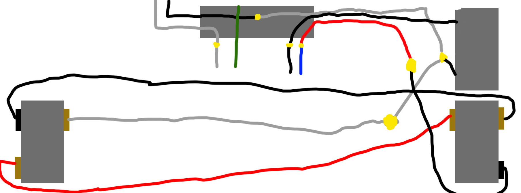
Excuse the crappy diagram, but I believe this is what I’m up against.
The top box is the fan controller. The white bundle (with no tape) is hot with 1 wire going to the fan controller. The other wire for the fan controller goes up to the fan. The red/black bundle is off the common terminal of the switch below it. Black comes up, red goes to the blue wire (light) on the fan.
I’ll be glad to help you figure it out. A couple questions to start.
1 - This is a panel to the fan configuration? In other words, you have a constant hot over a 2-wire Romex going into the fan box first?
2 - There is a light and a fan?
3 - Two switches control the light via a 3-way configuration?
4 - In addition to the 2-wire power feed, there is a 3-wire Romex in the fan box?
5 - Is that 3-wire in the fan box going to the fan controller (top right in your diagram)?
6 - What are the connections in the fan box? i.e. How are the 2-wire, 3-wire and fan/light connections made in the fan box?
I think I see what you have for the lights, but the connections in your diagram between the two switches don’t look right. I’m thinking the white at the Main/Left switch is connected to the black common terminal on the switch, but can’t tell from your picture.
@Bry
1 - This is a panel to the fan configuration? In other words, you have a constant hot over a 2-wire Romex going into the fan box first? Correct
2 - There is a light and a fan? Correct
3 - Two switches control the light via a 3-way configuration? Correct
4 - In addition to the 2-wire power feed, there is a 3-wire Romex in the fan box? Correct. There are multiple 2-wire plus a 3-wire in the fan box
5 - Is that 3-wire in the fan box going to the fan controller (top right in your diagram)? Correct. Black connects to the fan controller. Red connects to the black on the common terminal of the light. White(Hot) connects to the white bundle and the other side of the fan controller
6 - What are the connections in the fan box? i.e. How are the 2-wire, 3-wire and fan/light connections made in the fan box? White to neutral. Green to ground. Black to black from the fan switch. Blue to red from the fan switch box which goes to black on the common terminal of the right-side light switch
I’m thinking the white at the Main/Left switch is connected to the black common terminal on the switch, but can’t tell from your picture. It is definitely not connected to the common terminal. Being hot I assumed it would be as well. My understanding of a 3-way switch is that the common terminal either accepts the hot wire from the panel or outputs the switched hot wire to the light. This one for some reason is not like that.
As I sit here and look at this, I’m not sure I’ll be able to do what I’m planning to do without having to drop another wire from the fan to the fan-controller box. I would need a 4-wire to be able to bring the neutral down to the switches.
1-neutral
2-power
3-fan switch
4-light switch
I could setup the lights as-is in a non-neutral setup with an aux switch, but then I’d need to be on the hunt for a non-neutral fan controller which I don’t think exists.
Yep, you would have a non-neutral for the lights, as that’s how it goes with power to the light first. If you wanted to go with Inovelli’s combo, off the top of my head you ought to be able to go with that. It just needs power at the fan and the switch. You already have power at the fan and can send it via the 3-wire to the switch. And then get something to the other switch depending on how you want to do it.
I think the kinks are still being worked out of the combo, but installation-wise it should be easy.
I’m still not following you on the connections in the fan box. You have a constant hot feed via a 2-wire, bundled because it’s sending power downstream.
In your diagram, I see the black conductor of the constant hot is connected to the white of the 3-wire. That white goes to the top (fan) box but the red and black go to the bottom box? Or did you just take a shortcut and eliminate a pigtail between the two boxes?
In any event, the white 3-wire between the two boxes remains the constant hot. That’s correct, as you typically send the unswitched hot to the far end to return the switched hot to the first box. And you are right that that white, being constant how, should be connected to the black, common screw.
I can’t see how that would work as you’ve drawn it. I’d pull that switch on the left and test the throws with a continuity meter, but the screws look like they are in the proper places.
Maybe there is a color translation between the two boxes on the right? Also, you tested that far right white with it disconnected from the switch, right? Just trying to understand this.
The black of the constant hot is connected to the white of the 3-wire up in the ceiling. If you look real close at the black wire bundle sticking out to the right side of the ceiling fan you can see the white wire tucked in there. This goes to the fan control box into a bundle with a black that goes to one side of the fan controller. There’s also a white in that bundle which goes to the light switch box below it, into another white-wire bundle and off to the main switch on the left.
The red from the 3-wire connects to the blue at the ceiling fan. Then goes to the fan control box where you can see it bundled with a black wire which goes down to the light switch box below it and is connected to the common terminal.
The black wire from the 3-wire connects to the black at the ceiling fan then goes to the fan control box and connects to 1 side of the fan controller.
I assume so, but the switch on the right with the fan controller is buried behind a headboard (hence why I’d prefer the aux to be in this position so we can use the pretty LED). I’ve honestly never flipped the switch since we’ve moved in.
EDIT: NOPE! That switch on the far right does nothing. I’m going to pull apart the switch on the left now and swap that white wire to the common terminal like I think it should be.
EDIT 2: Swapped the white and black wires on the switch in the far left. Both switches now work. I should have trusted my gut on this one and did it when I put it back together. So white (hot) wire is now on the common terminal.
non-neutral switch config will get me going with lights today but will leave me in the same mess when it comes to a fan controller down the line.
fan/light combo switch would leave me with a dead plate, which kind of sucks, but it’d be behind a headboard which makes it livable.
Any idea if the fan/light combo can be used in a 3-way config for the light OR work with z-wave association? (@EricM_Inovelli) Adding the RF module in the fan canopy would free up a wire in that 3-wire bundle so I’d be able to bring neutral down to the switches without having to run new wires.
I could also use white for neutral instead of having a bundle of white wires that are hot and have no tape on them! I was original pissed at the electrician when I found that, but if one of the wires on the switch was swapped, I assume the previous owners had it apart for some reason and they may have peeled the tape off the bundles so I’ll let this one slide lol