Models: Red-Series VZW31-SN + Inovelli Add-on/Aux Neutral: I have neutral wires available and am attempting to utilize them. Setup: 3-Way
Hello, I’m having a whale of a time getting my new Red-Series VZW31-SN to work in a 3-way instance with an Inovelli Add-on/Aux switch.
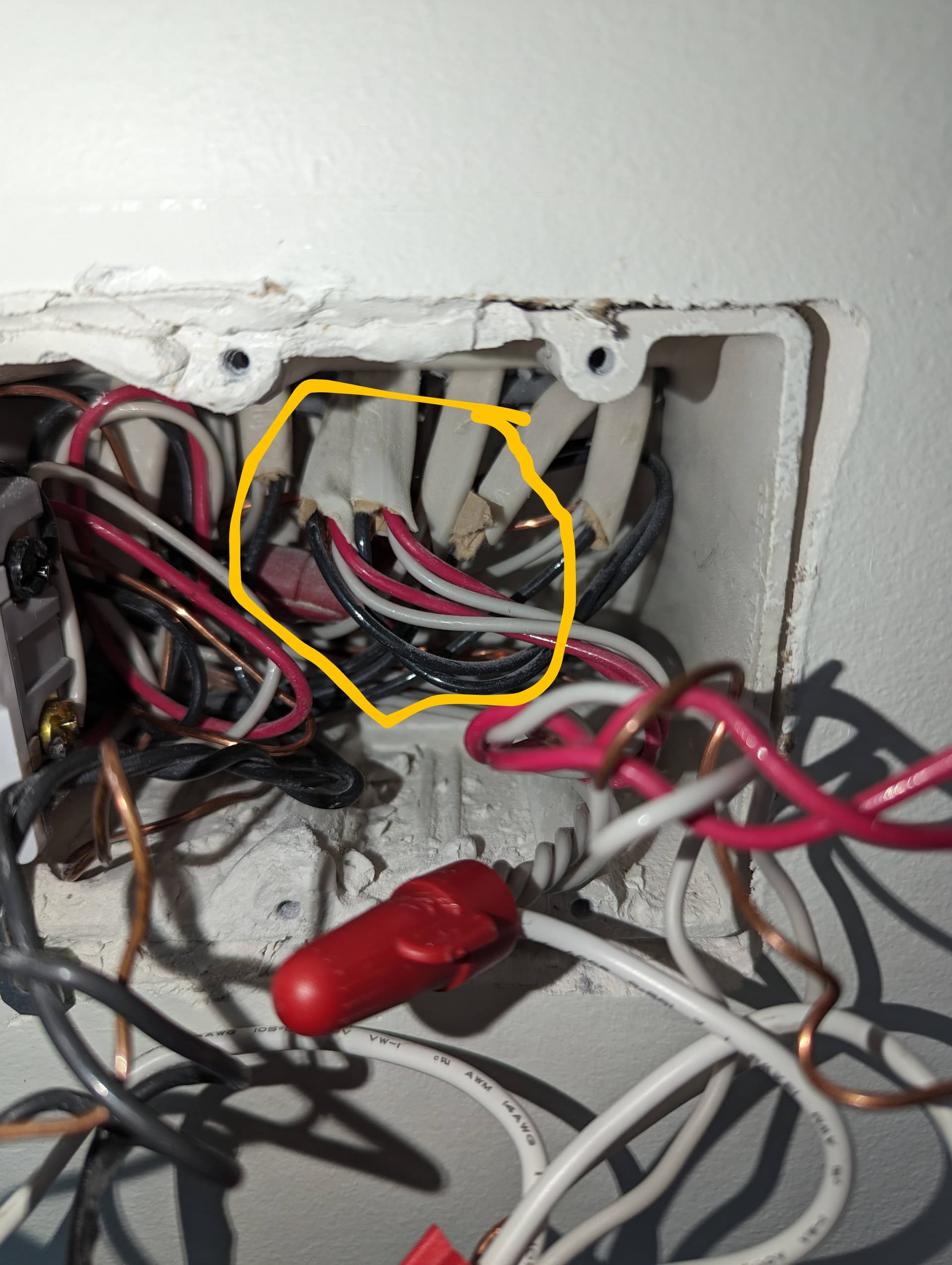
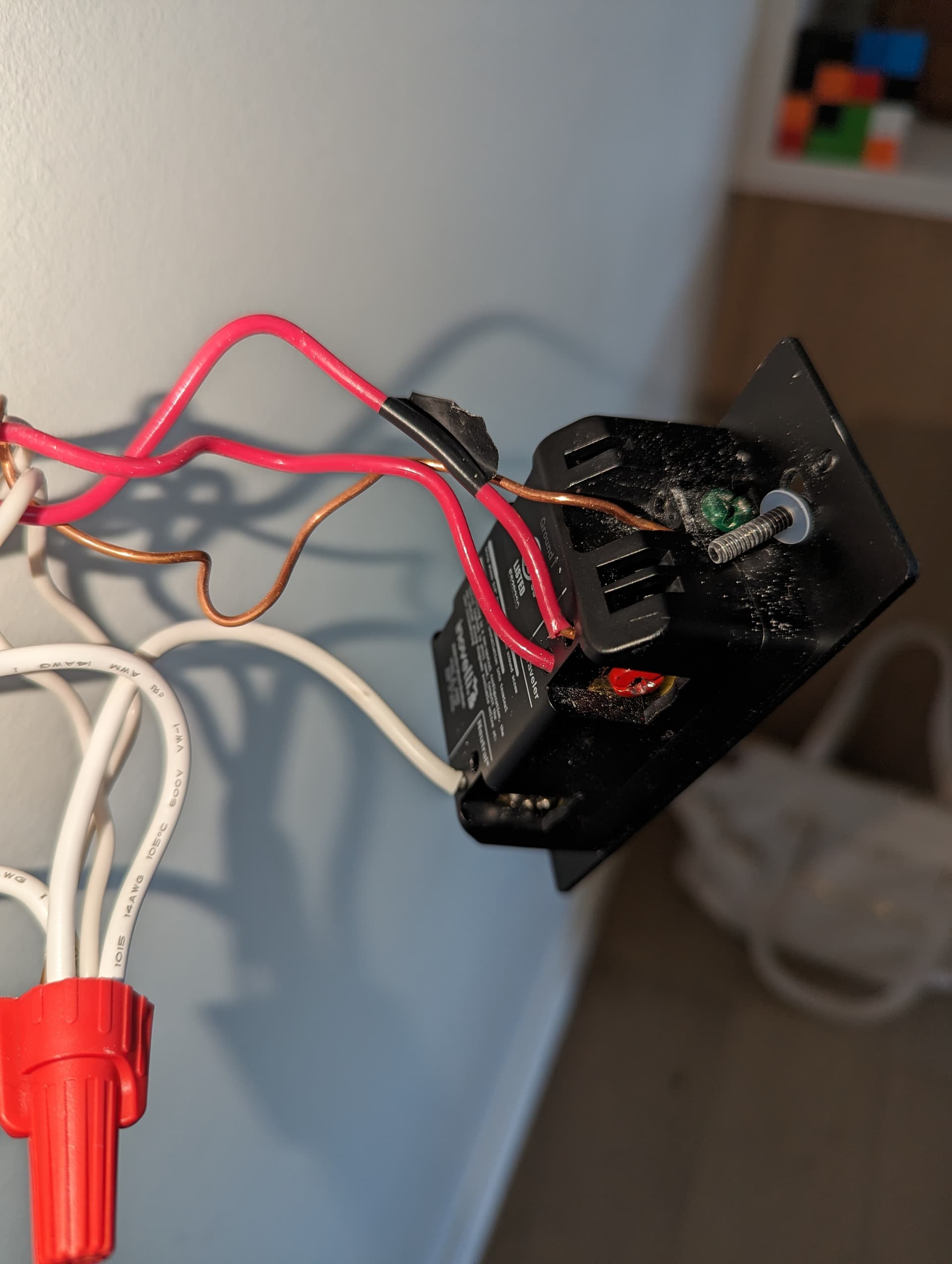
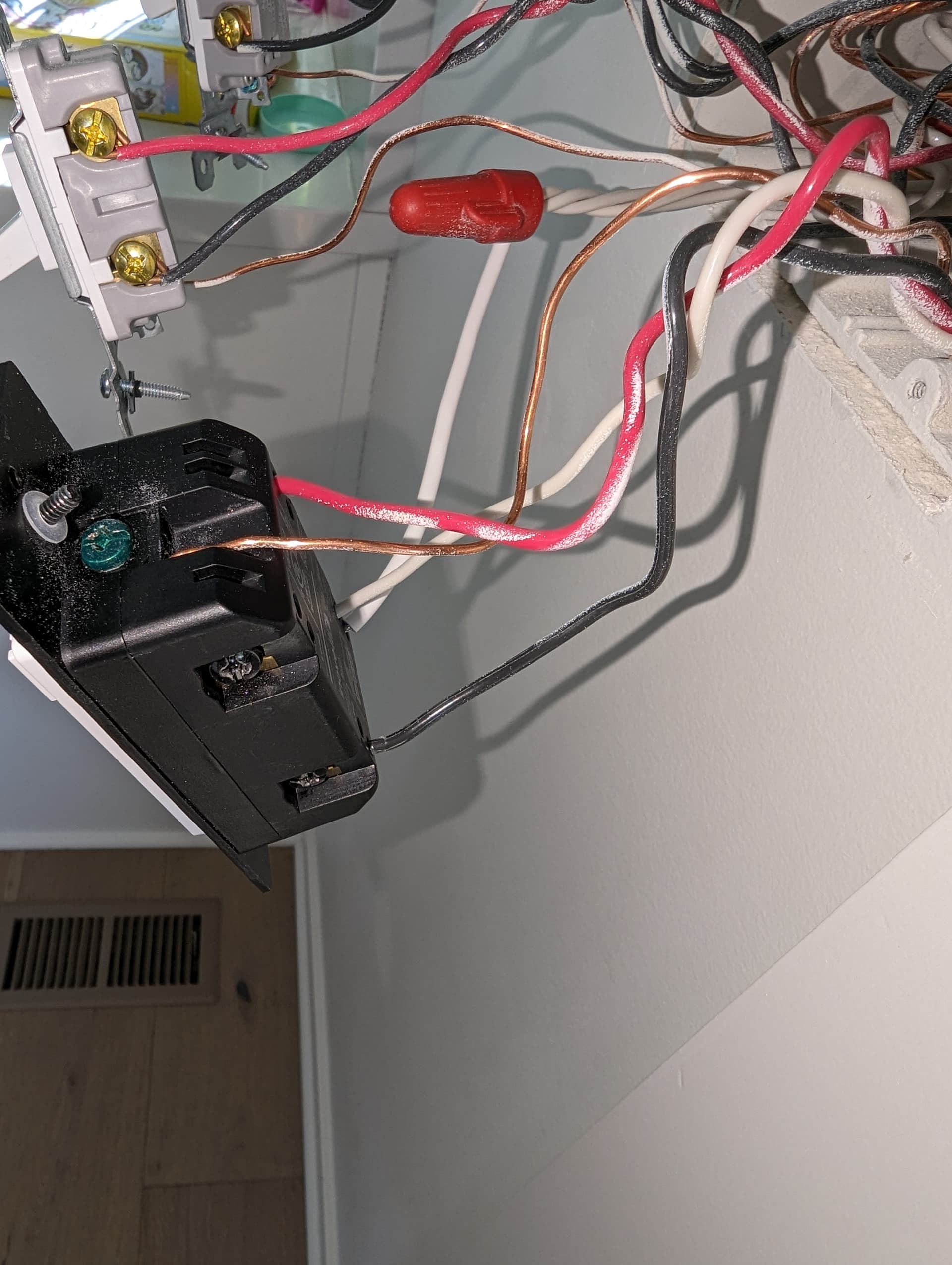
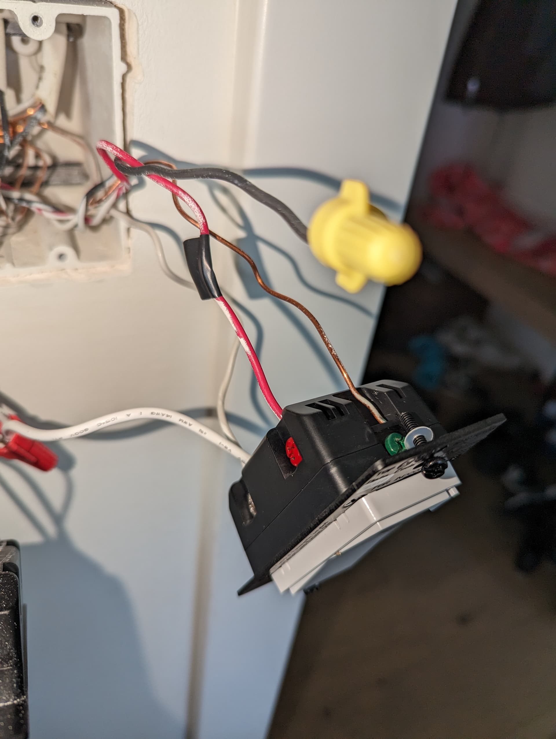
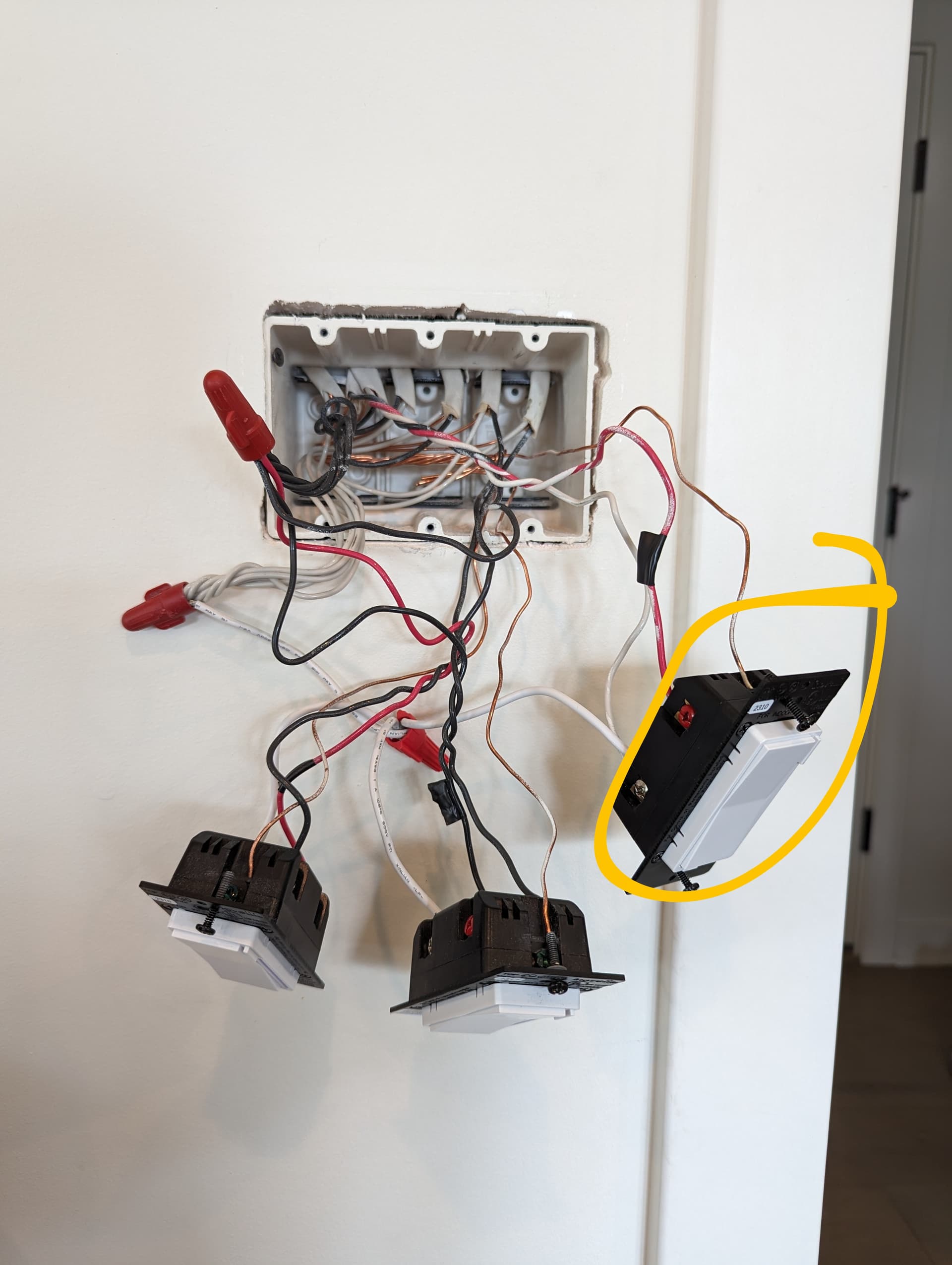
I think what’s causing me trouble is that my wiring in the wall includes 2 red wires which differs from any of the wiring diagrams.
As currently wired, the light functions from the smart switch but not from the Aux. I have already adjusted parameter 22 to be “Multi-Way with aux switch”.
The color of the wires doesn’t tell you what the wire is, unfortunately. They won’t match the wiring guides so you can’t go based on that.
For example, one of your red wires has black tape on it. Where I am, that indicates the wire is hot and will always be at 120 V unless you flip off the breaker.
You need to use a multimeter and test the voltage on each of the wires to really figure it out. You need to know which wire is the line (is at 120 V all the time), which wire is the load (goes to the light itself). Where these two are is crucial I think to figuring it out, as the two main setups are line and load in the same box and line and load in different boxes. You also need to figure out which wires are the travelers. And possibly other stuff.
@Bry will also need better pictures for when he comes in here with his genius wiring brain and figures it out. Go back and look at his comments on previous posts to see what he’s looking for in terms of photos. Then take more photos and upload them.
Pretty much what @UngluedChalice said about needing better pictures.
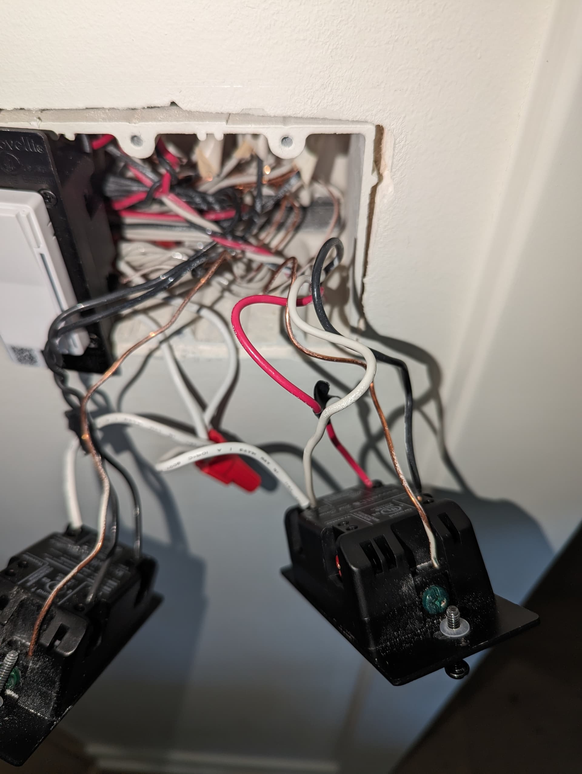
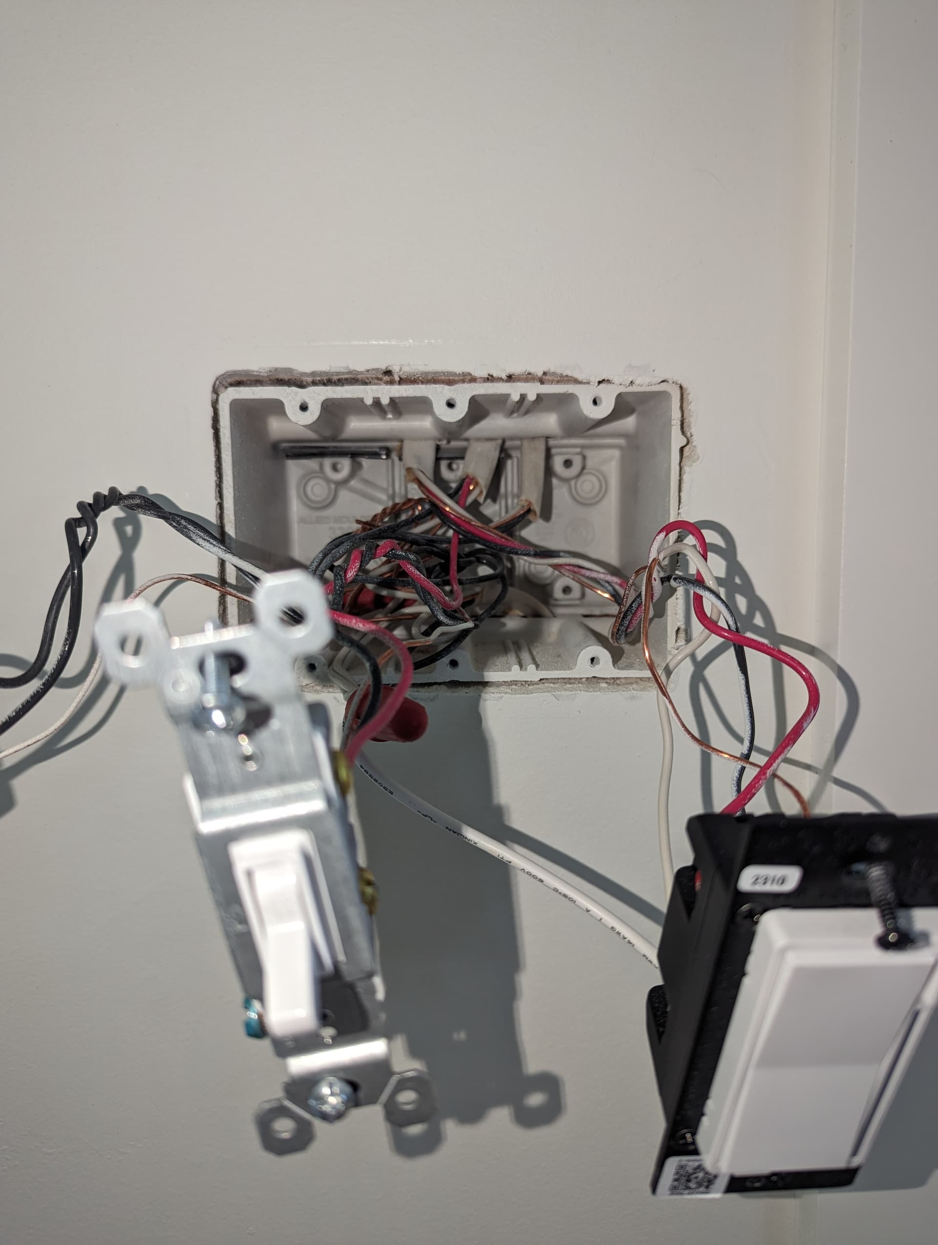
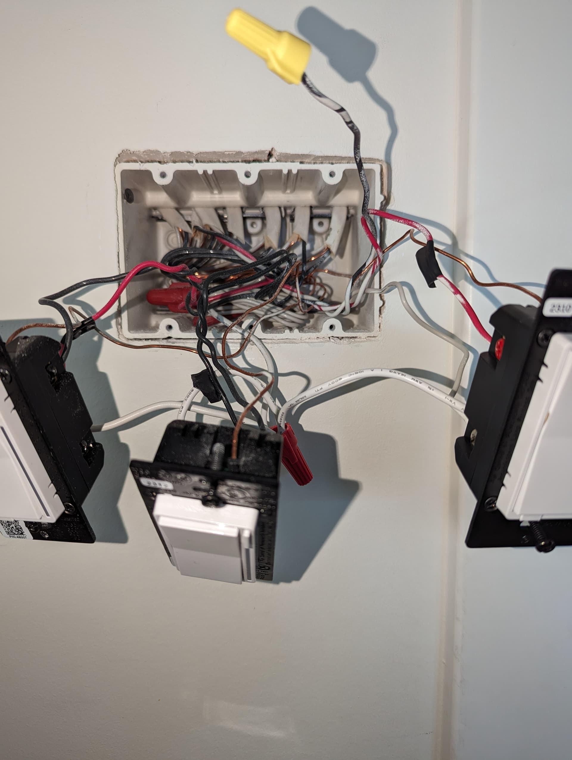
However, in the mean time, one thing that hits me is what you were asking about with the two 3-wires in the Aux box. That suggests to me that this isn’t a 3-way. Is there another switch (or more) you’re missing? While this sounds like a weird question, it wouldn’t be the first time the user has found more switches than he/she thought existed.
In a 4-way or more there are TWO 3-wires in the middle boxes. Do you have pictures of the switch you removed? Does it have four screws not counting the ground screw?
Oh crud! I think you’re right! I think it’s a 4-way. It’s inaccessible at the moment but I’ve got some additional images of the previously pictured switches.
So if you don’t want to use the last (or additional switches), in your Aux box, figure out which 3-wire is from the Inovelli and which is going downstream. Connect only the two conductors from the 3-wire from the Inovelli to the Aux. Cap off the third. Also cap off all three conductors from the downstream 3-wire. Leave that ground bundled.
Okay, you’re going to keep doing what you were doing with the aux switch, but you’re going to have to get that dumb switch out of there before it will work properly.
Okay, so pending the line from my breaker going to the correct switch first, and the dumb switch being swapped for another aux my current wiring looks accurate? Thanks for the help btw.
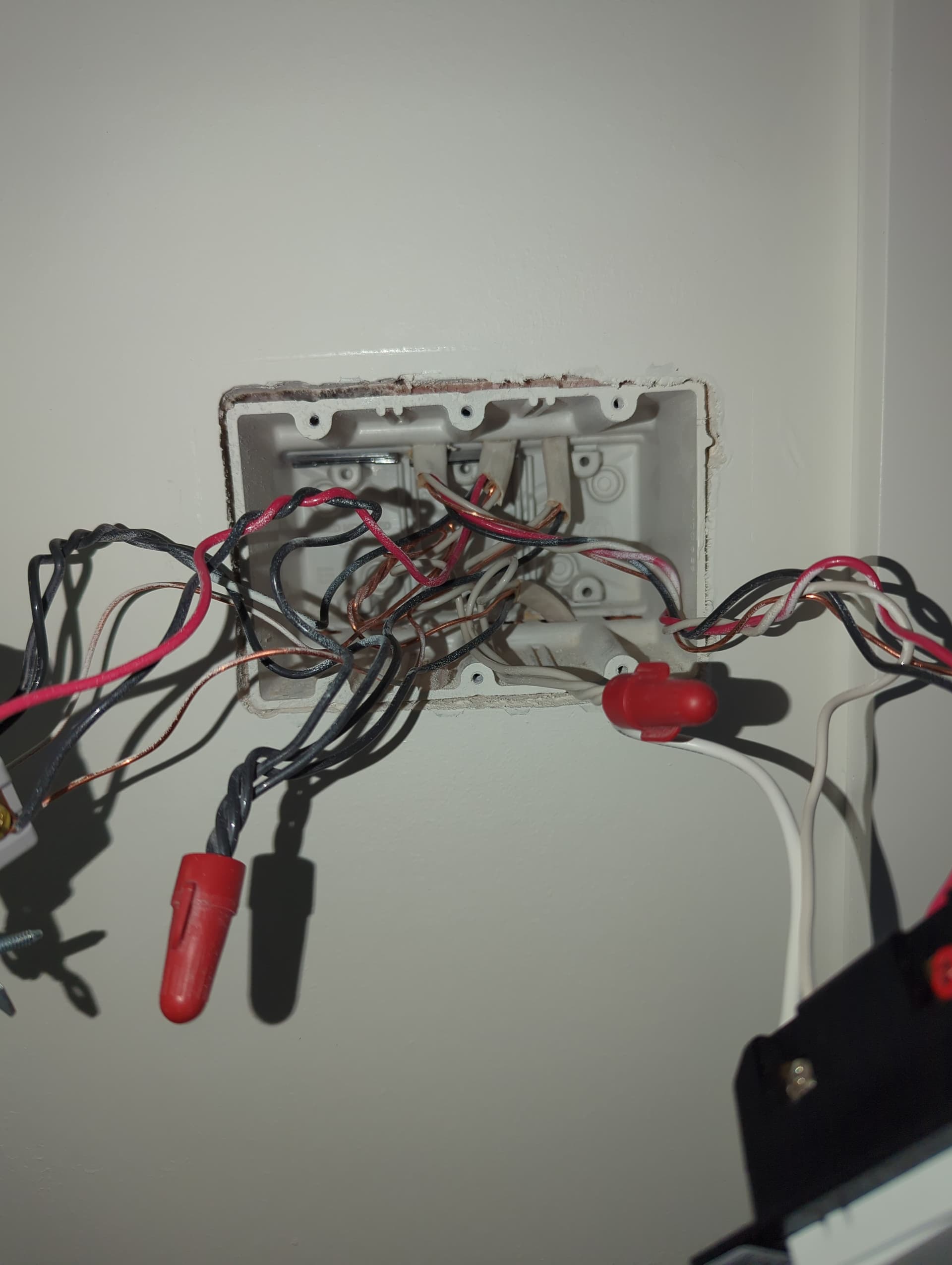
I didn’t look at the rest of it once I noticed that you didn’t have a 3-way, plus your boxes are difficult to see into.
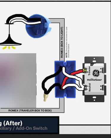
The best approach is to do this in stages. You said the Inovelli was working fine, so that suggests you have a line and lone in the Inovelli box. At the Inovelli box, disconnect the traveler from the 3-wire and put the switch in the 2-way mode. If it works ok, then you just need to add the Auxs.
Use the red and the white on the 3-wires and cap the blacks. At the Inovelli box, white to the neutral bundle and red to the traveler terminal. At the Auxs, red to the traveler terminal (use both holes for the middle Aux(s), and white to the neutral terminal (use both holes for the middle Aux(s). Set the Inovelli to 3-way momentary.
Thanks so much, @Bry. Identifying that other switch to make this a 4-way discussion felt like it was going to resolve my issue but it seems I’m not quite there.
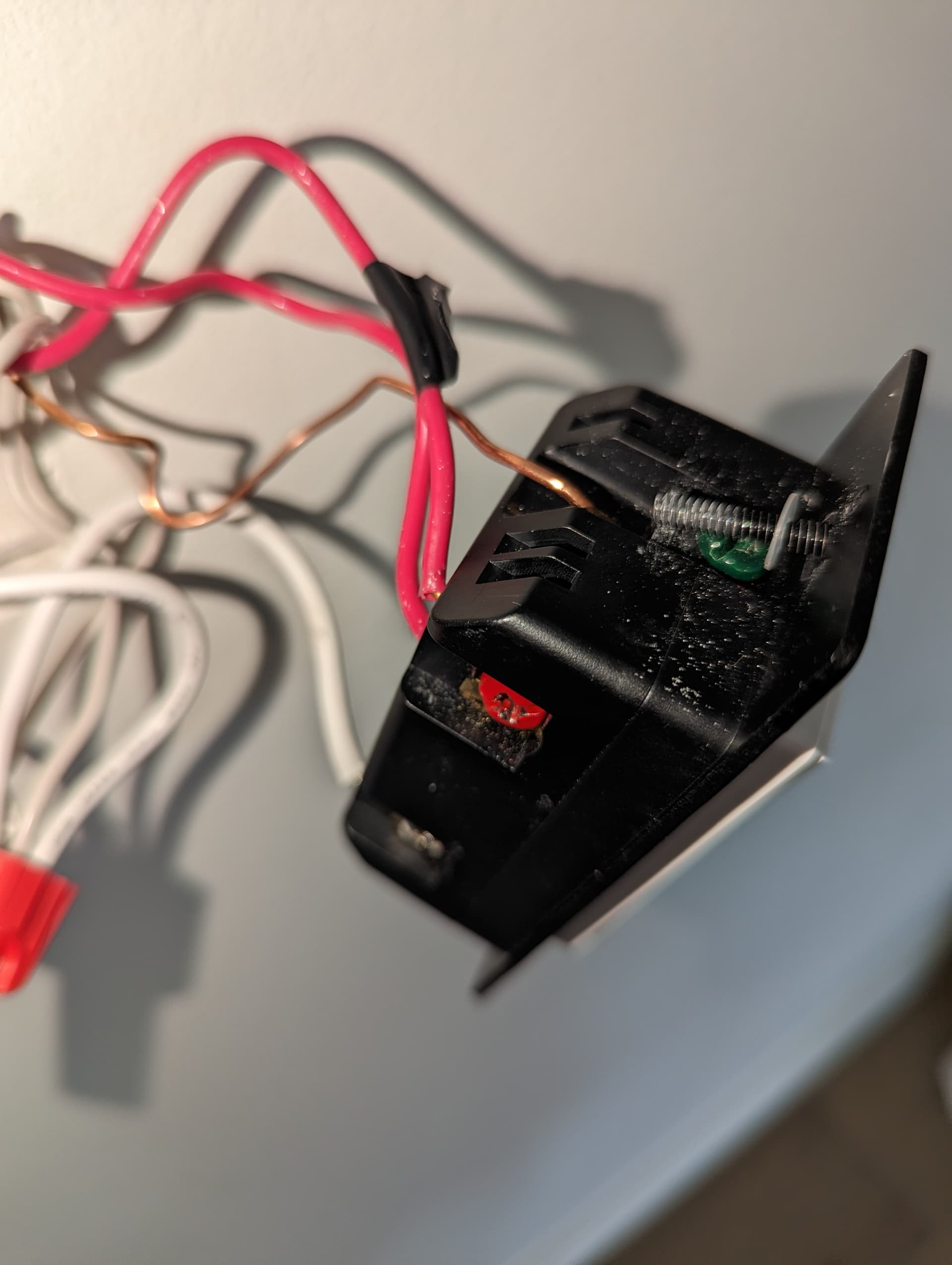
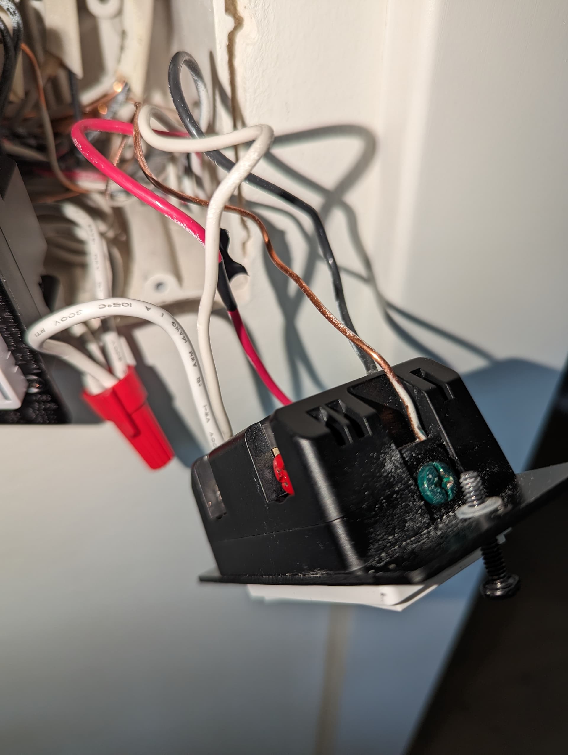
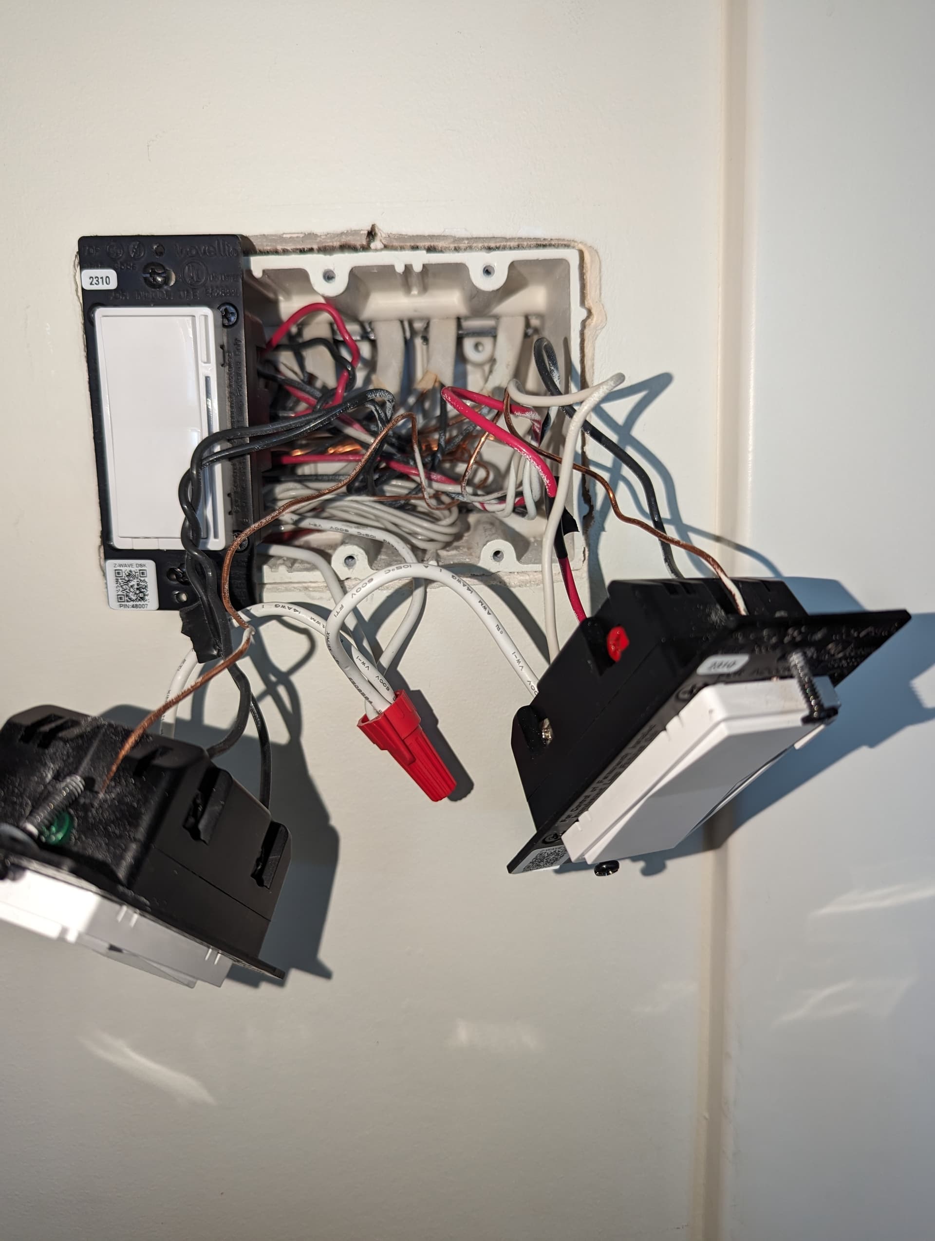
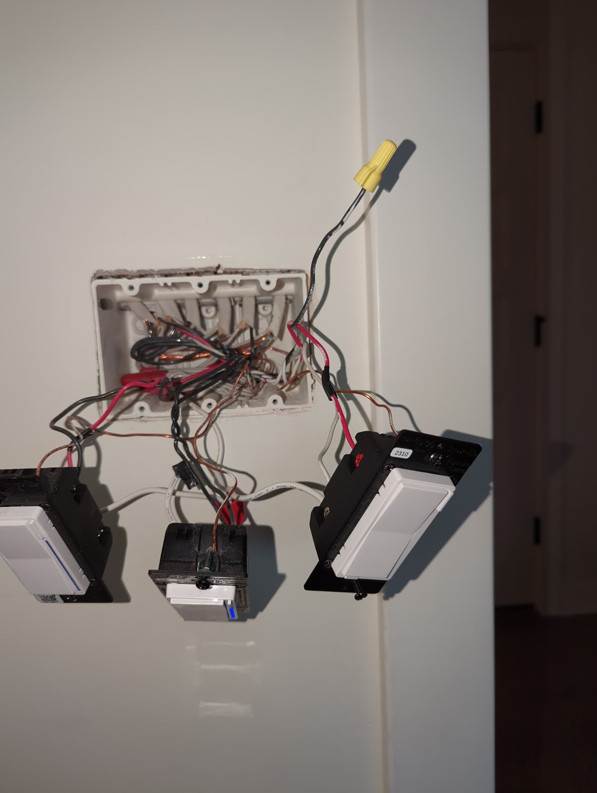
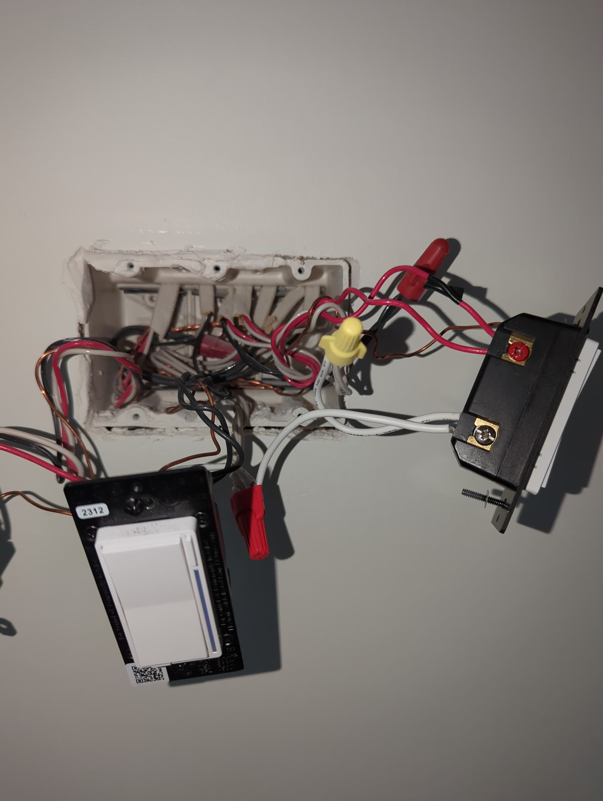
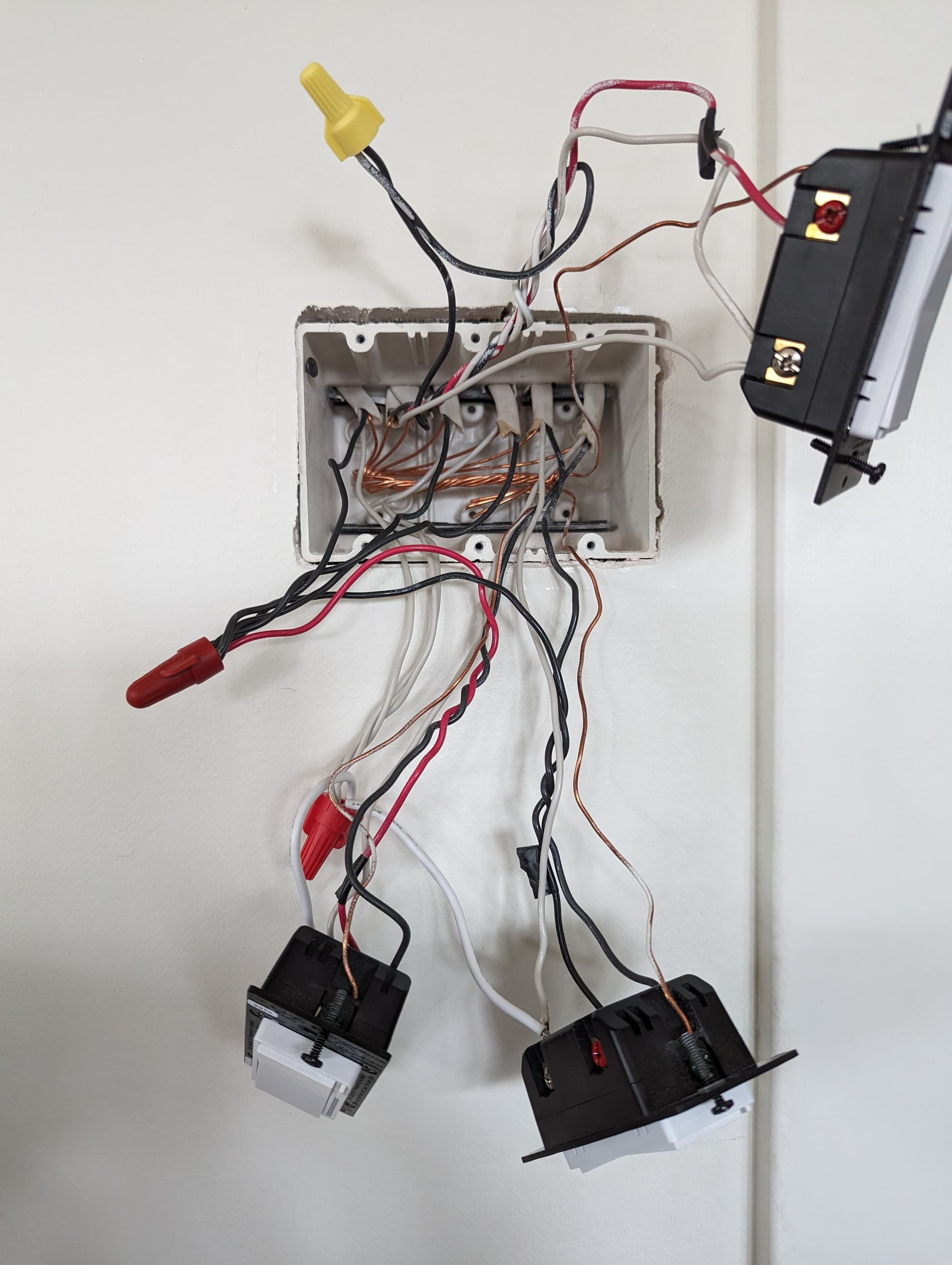
That previously unidentified switch is, I’m pretty sure, the initial switch with the line from the box so I’ve switched my smart switch there. I’ve installed Inovelli aux switches in the other two locations. I’m going to post images of each location. I hope I’ve gotten clearer views inside the boxes but can definitely take more.
In each gang, it’s the right-most switch that I’m currently trying to address.
You posted that this was working as a 2-way, right? So you apparently had a line and a neutral to power the switch, and the load must be in that box. So why did you switch it?
Yes, I’ve confirmed that the previously unidentified switch (now the smart switch) IS the 120v constant.
When it was previously working, it was just functioning from that one location and not the other two and I assume it was only working from that smart switch in that instance is because it was open in the unidentified switch.
After moving the smart switch to the box with the 120v constatant, as pictured above, it does not control the light independently (I updated parameter 22).
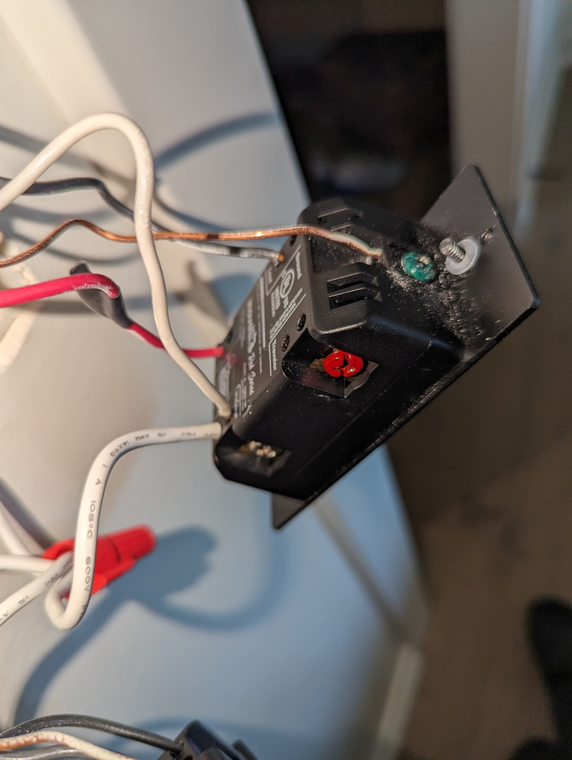
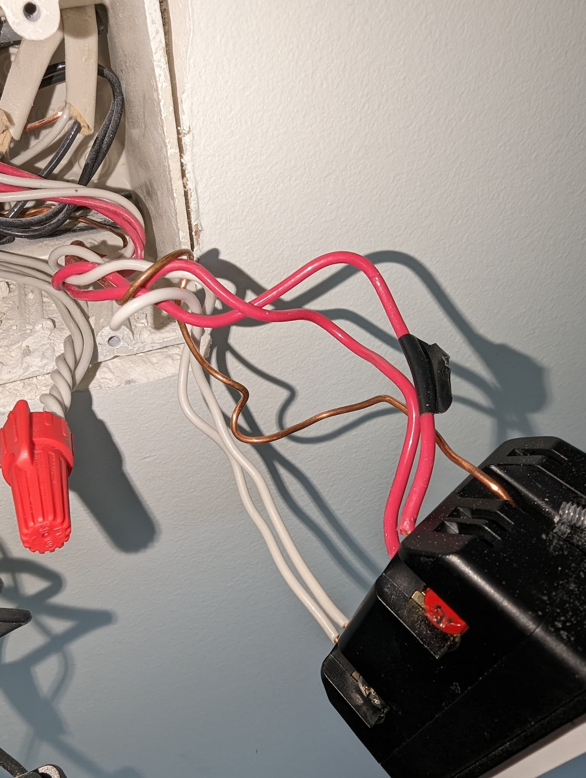
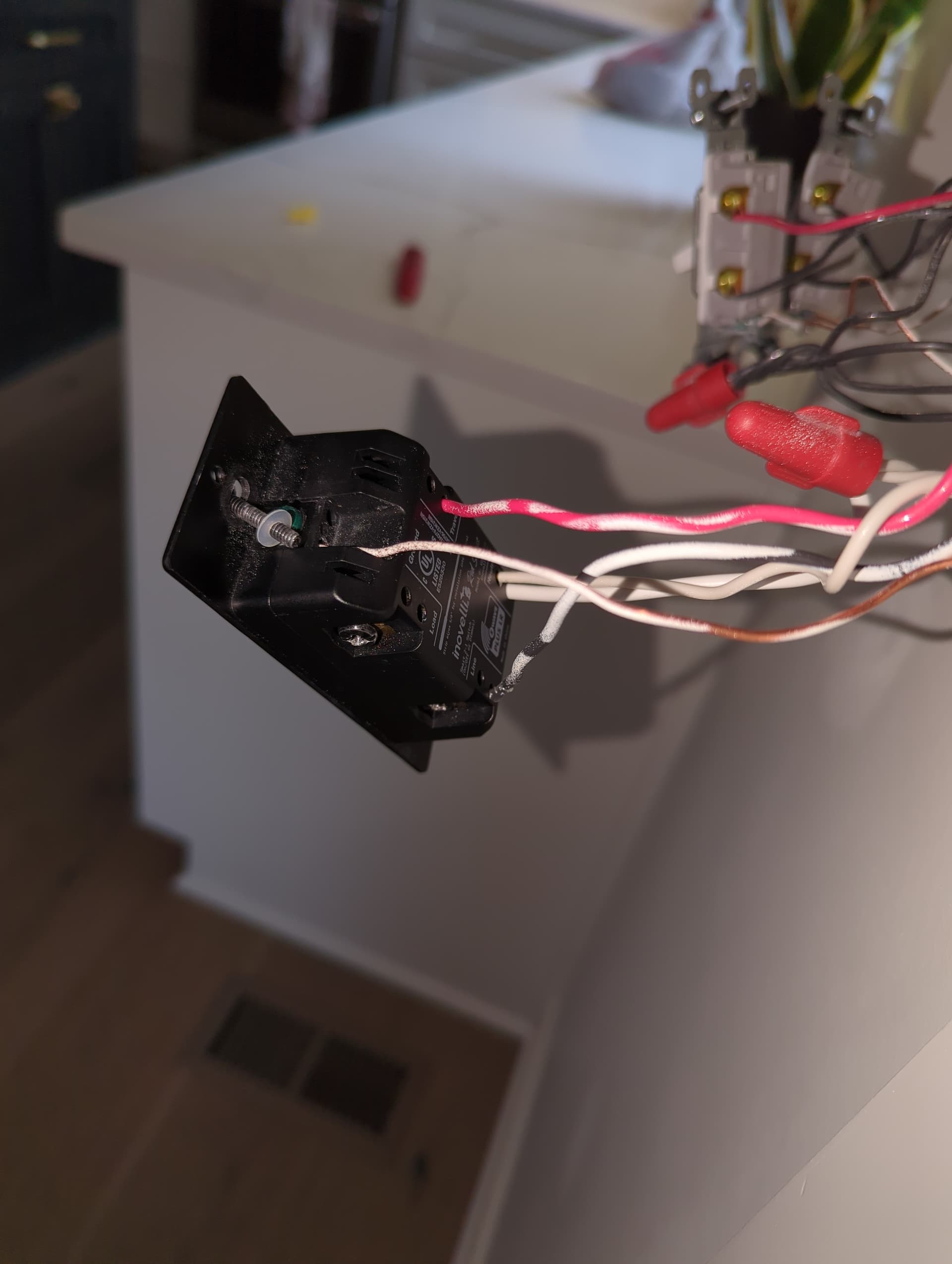
@Bry Where I think I’m running into an issue is that the box with the 120v direct line, there is no load wire just the line, traveler, and neutral. (this is where my smart switch is currently)
Got it. So this is a 4-way switch leg, which means you have three switches.
You want to put the Inovelli in the box with the Line. In the other two boxes, you will use Aux switches. The load is in one of the two Aux boxes.
At the Inovelli box, power the switch by connecting the hot and neutral to the line and neutral terminals.
You will have 3-wire Romex between the three boxes. At the Inovelli box, connect the neutral to the white on the 3-wire (use the 2nd hole on the switch). Connect the red on the 3-wire to the traveler terminal. Connect the black on the 3-wire to the load terminal.
So that will send a neutral, traveler and switched load to the next Aux box. At that middle box, connect the red traveler to the traveler terminal. Connect the white neutral to the neutral terminal. Also connect the same colors from the 3-wire going to the last box, using the 2nd hole. I don’t think the load is in this middle box, so just connect the black on the two 3-wires together, sending the switched load to the far Aux box.
At the far Aux box, red to traveler, white to neutral. Also connect the white from the 2-wire load Romex to the neutral terminal, using the 2nd hole. Connect the black on the 2 and 3-wires together, sending the switched load up to the light.
Please pay close attention to what I wrote previously or follow the diagram. If this is too difficult to follow you might want to consult with an electrician.
There is no load wire in the Inovelli box. That is why you send it over the black of the three wire.
Why did you cap the 3-wire black in the last box? It should be carrying the switched load, so it needs to go to the light.
@Bry thanks for your patience. I have finally, actually this time, gotten this word as you directed but now the lights are on, switch is powered, but they won’t turn off.
I double checked parameter 22 was set correctly and it is.
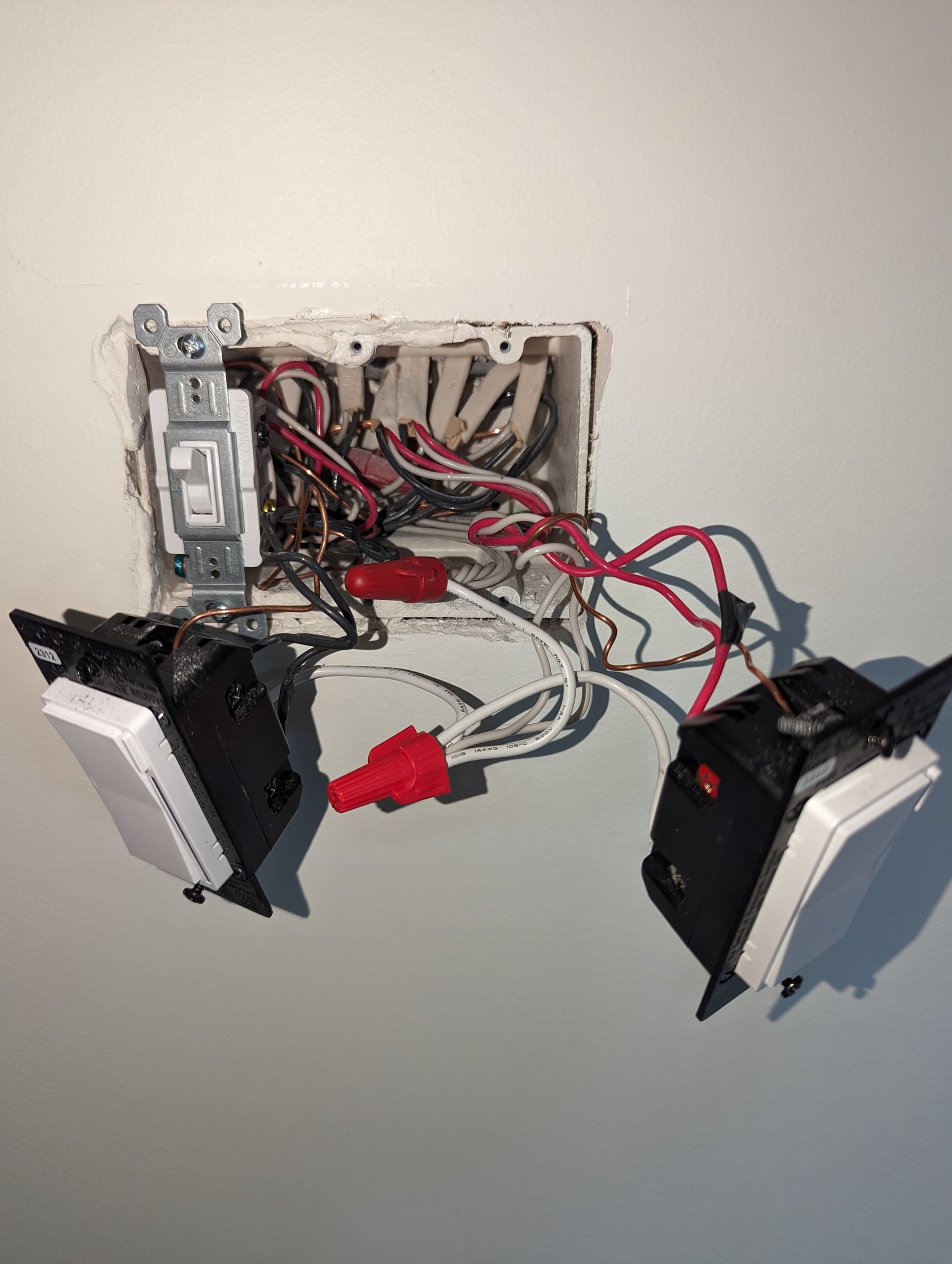
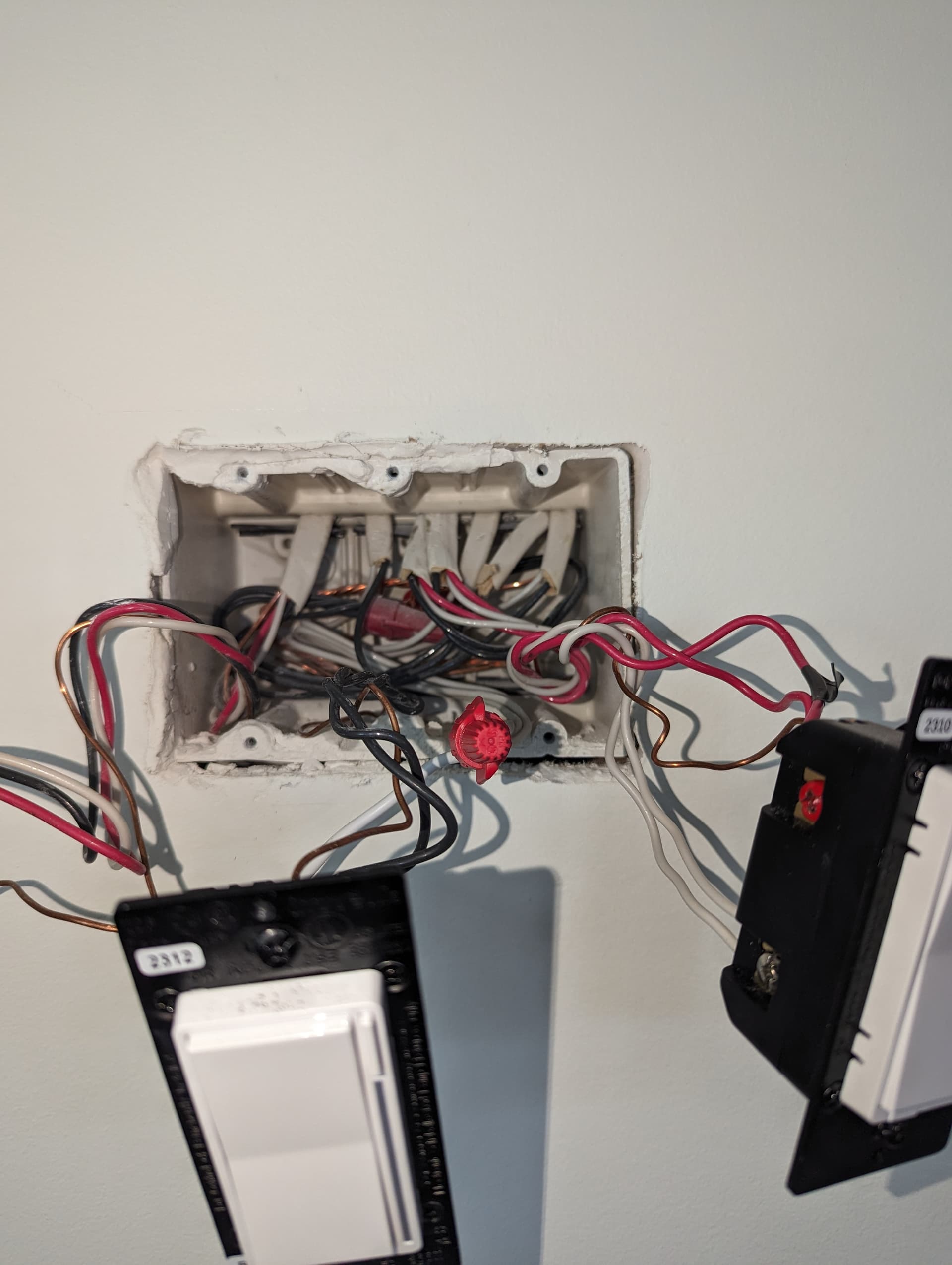
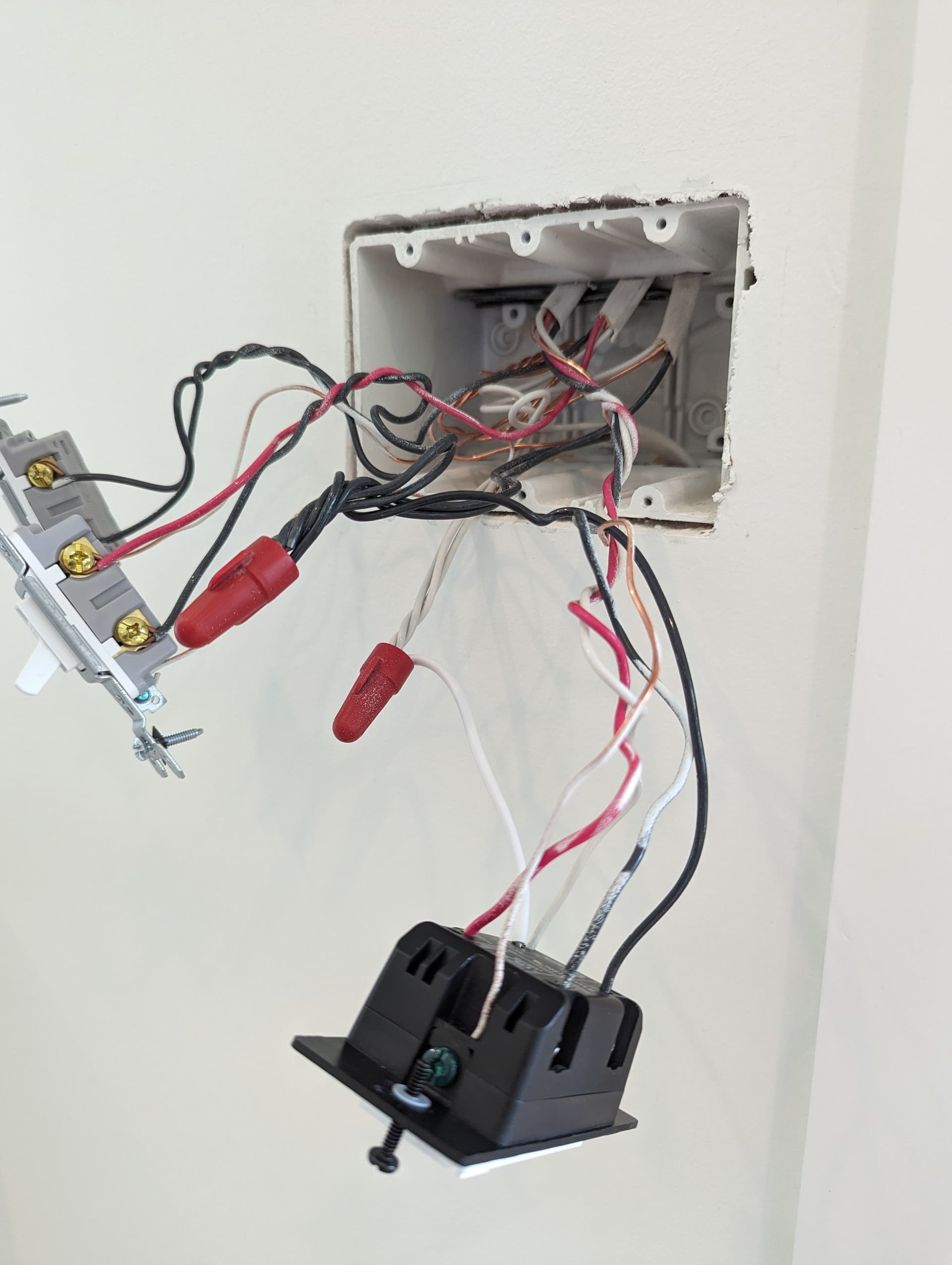
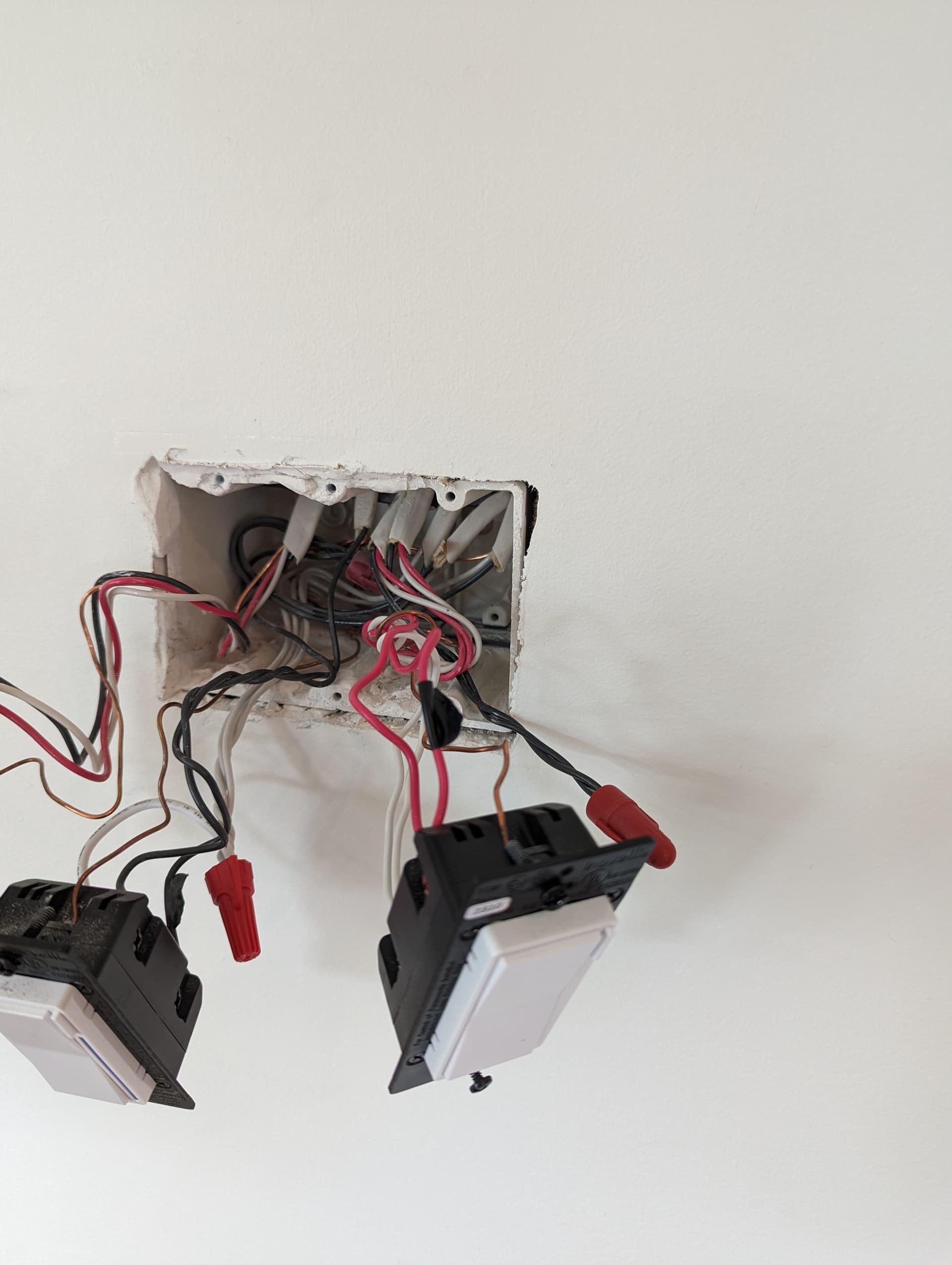
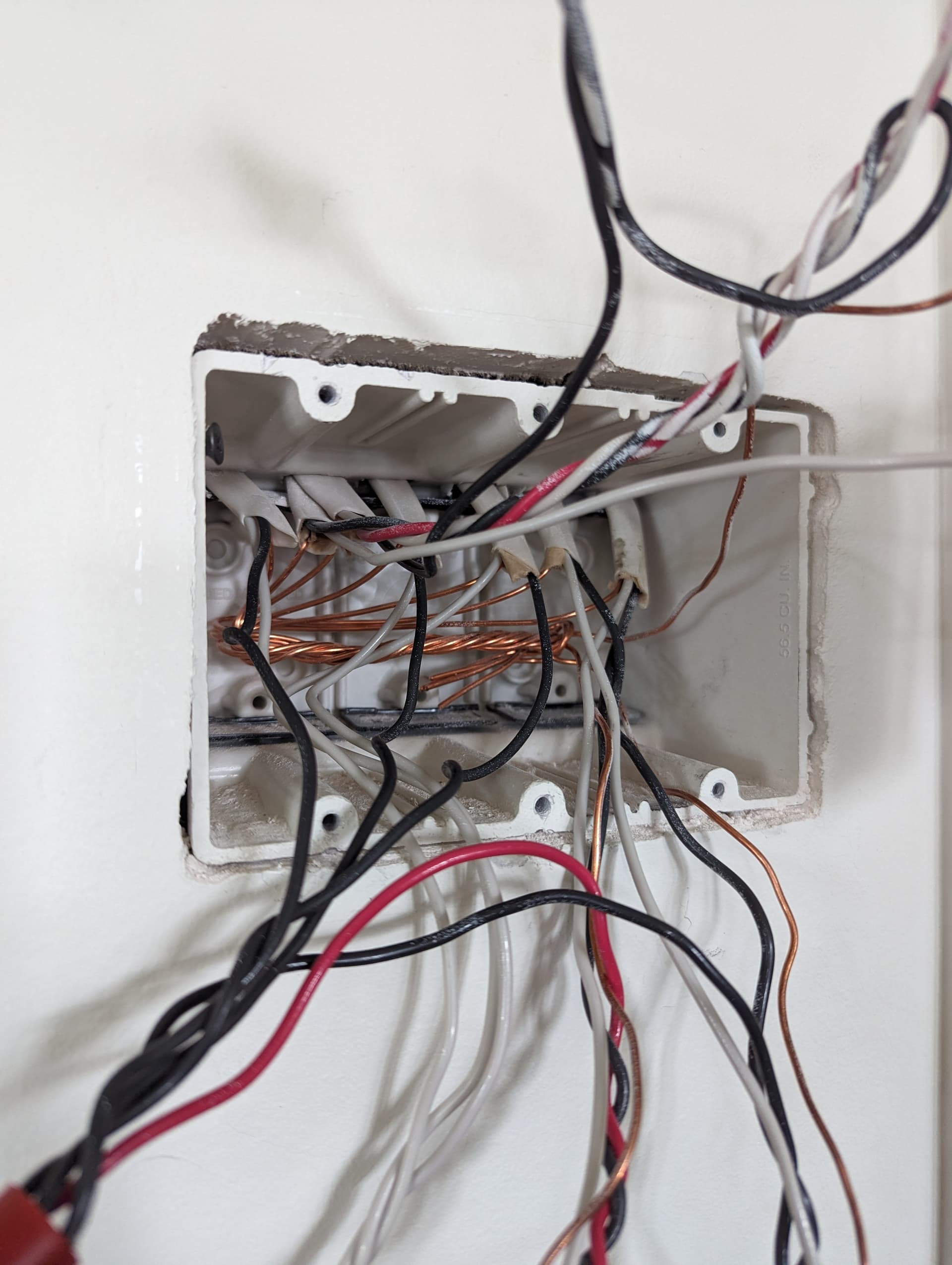
I’m not quite sure what you have going on in the 3rd box (the other end from the Inovelli). I can’t see enough of the individual conductors in the rat’s nest to see what you did. The best I can tell you at this point is to explain what I’m not seeing.
So when you wire these, you have to understand the concept of the operation. The Inovelli is the controlling box, but the load is in the far box. So you are sending three things over the 3-wire to the remaining to boxes. The Aux’s need a neutral and a traveler, so those go over the white (neutral) and traveler (red). Because the load (i.e. the light) is in the far box, you have to send the SWITCHED hot from the Inovelli to the third box.
So at the third box, there are two Romexs involved. The first is the 3-wire from the middle switch and the other is the 2-wire going to the light.
So, referring to the diagram posted earler, the 3-wire conductors should be:
White (sent neutral) to the neutral terminal and red (traveler) to the traveler terminal.
The black from the 3-wire is the SWITCHED hot. That should be connected to the black from the 2-wire going to the light, effectively letting the Inovelli control it.
I can’t see what you did with the black from the 3-wire, but it doesn’t look like it’s going to the 2-wire load. I would expect to see two blacks tied together, but all I see is one big black bundle, which can’t be correct.
Also, the white neutral pertaining to the switch leg was sent from the Inovelli box. To get the neutral to the light, it needs to be tied to the white from the 3-wire, which you can do using the 2nd hole on the Aux. You have a white going from the 2nd hole of the Aux to what looks to be a neutral bundle, which isn’t correct. That may not even be the proper neutral for this leg. I would expect to see the white from the 2-wire load connected to the the 2nd hole of the Aux, but that’s not what you did.
To recap:
1- Tie the black from the 3-wire and the 2-wire load together (AND TO NOTHING ELSE).
2- Remove the jumper from the Aux to the neutral bundle. Find the white from the 2-wire load and remove it from wherever it is, and connect it to the 2nd hole on the Aux.