Hi all -
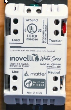
I recently got a 5 pack of the VTM31-SN. I installed two of them in a single pole configuration and it worked well! But I had two that were in 3-way configuration and I had a bad experience with them.
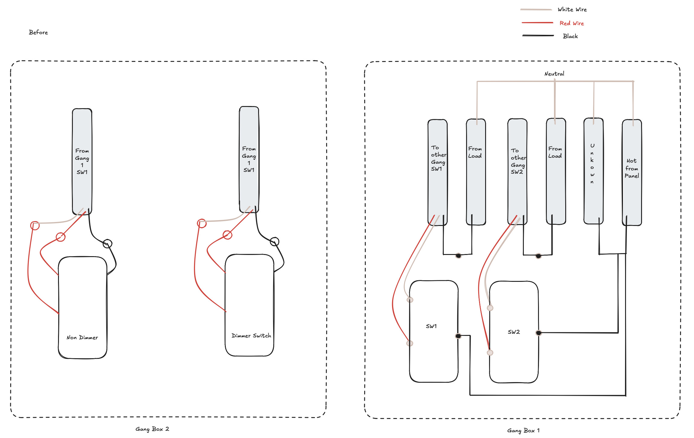
See my wiring diagram below to help with the narrative…
I initially wired up sw1 with the guts of the gang box exposed. I just wanted to make sure the wiring worked. It did work and I was able to validate the setup both in the Inovelli switch as well as the dumb switch I paired with it. Of course because the dumb switch worked, means I was able to configure the Inovelli switch by pressing the down button and hitting the config button 5 times.
Seeing success, I wired up the second one in the gang the same way, the gang box was tight so I had to push things in a bit and then I finally closed it.
I turned the breaker on; the second Inovelli switch also came up. I went to configure it in a 3-way setup with a dumb switch, and the moment I got the confirmation LED light, I heard a small hissing sound followed by burning smell.
Immediately tripped the breaker off.
I pulled out the bad switch out (sw2), with the wires exposed, I turned on the breaker again and I tried toggling the other switch (sw1), and within seconds even that made a hissing sound and went out.
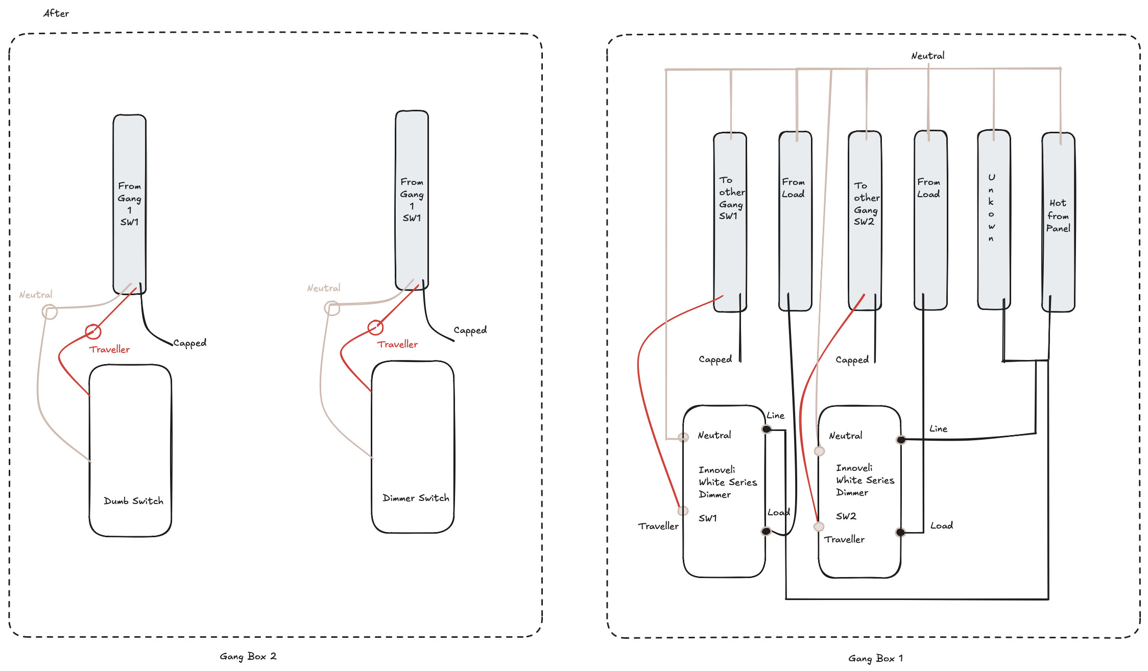
At this point, I reverted the config back to two dumb switches …
Below are my wiring diagrams of what I did.
I want to get confirmation that the wiring diagram is correct?
If it is, then I am blaming the fact that I jammed all those cables in and maybe caused some short somewhere.
Any feedback would be much appreciated.
Gang box 2 is very clean; it only has 2 Romex cables coming in and nothing else. Of course there is no hot here. but curious if there was any way I could put the Inovelli in the 2nd gang box with more space?
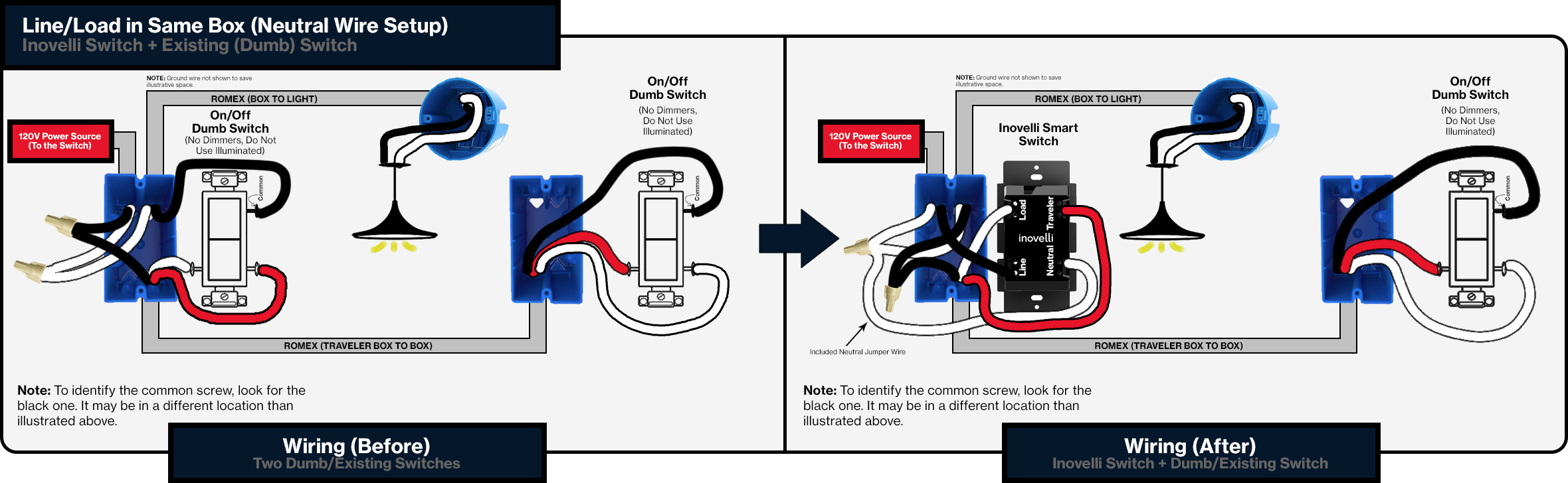
![[scenario 1]](https://downloads.intercomcdn.com/i/o/799247969/1b37bd5a3f540813cd39b59c/Inovelli-2-1-Blue-Series-3-Way-Pole-Neutral-Installation-Line-Load-Same-Box.png?expires=1771918200&signature=b7a232624260a118fb7e1cdaaa7c7d03677dfed0f7870c569a10d2d25af3890c&req=cykuFM15lIdWFb4f3HP0gLuzJatYj5j7OJTW89UfNc6Z5FDuBDjDbbAsQOEC%0Abqc%3D%0A)