So here’s the meat of it. I don’t have any idea what’s going on at the light itself. There’s 3 14/2 conductors in the light fixture box, and only 1 14/3 conductor in each of the switch boxes. The only thing I can think of is that the wires running to the switch boxes must come from a junction box in the attic somewhere or something.
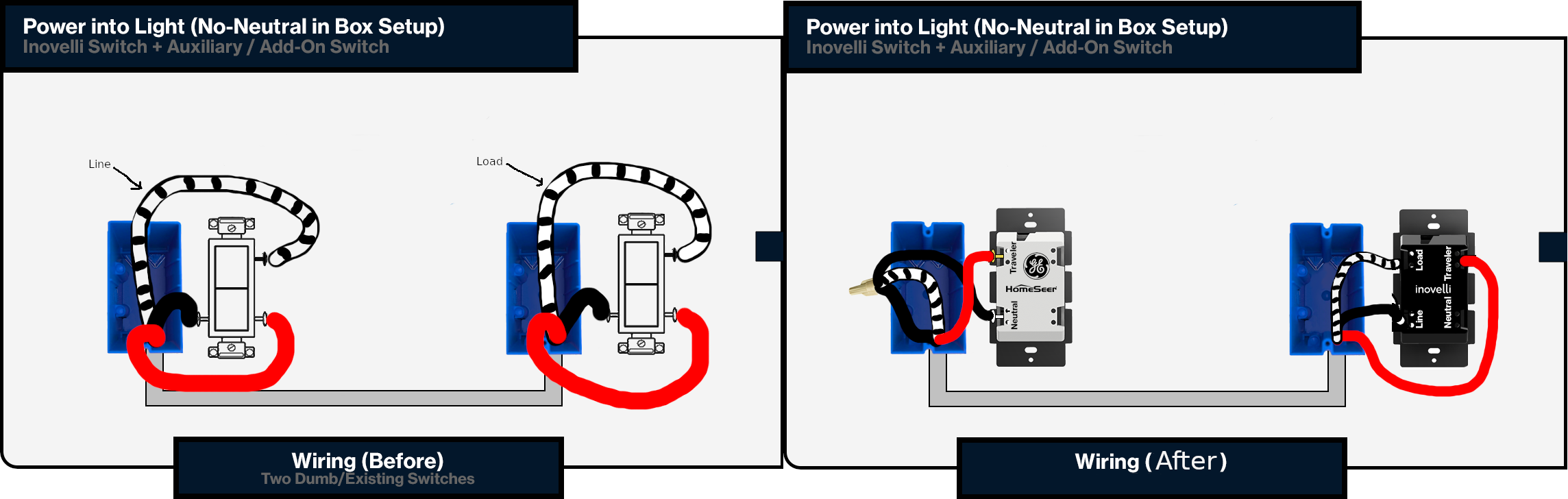
In any event I figured (and perhaps incorrectly) that it doesn’t matter. As long as I have a line, load and traveller connected to the inovelli switch, and a line and traveller on the aux switch I should be good right?
That wiring makes sense to me. And after connecting it and turning on the power it sort of worked. The switch rebooted itself a few times and the light wouldn’t turn off, etc so I figured the 3 bulbs in the fixture wasn’t enough load so I put in a dimmer bypass and tried again. This time nothing. The LEDs on the switch didn’t even light up. So I thought ok, maybe I got a dud switch? So I wired in another the same way and it worked properly. I paired it with my zwave network, set the options turned the light on and off, etc and all was working nicely.
At this point I didn’t have the light fixture or switches secured in the box, so I killed the power again put everything back together, and when I turned the power back on, now the light doesn’t turn on, and there’s again no LEDs on the switch!
So I’m stumped. Even if I call an electrician (I plan to for other stuff anyways) I don’t know what to tell him. I WOULD have told him to just get a line, load and traveller on the switch and a line and traveller on the aux and it should be good… but it seems that’s not the case?
Any anyone shed some light on what might be going on? Or even what I can tell an electrician when I call one? I’d like to stop frying switches.
We’re going to need pictures to diagnose this. Seems like line goes to the light then drops down to one of the switches. Then crosses over to the other switch through the light fixture. Ultimately coming back to the light as a load.
10-4. Just to be clear though there’s only one light fixture. I can get some pictures of it tomorrow night. Getting a little late for monkeying around with it now
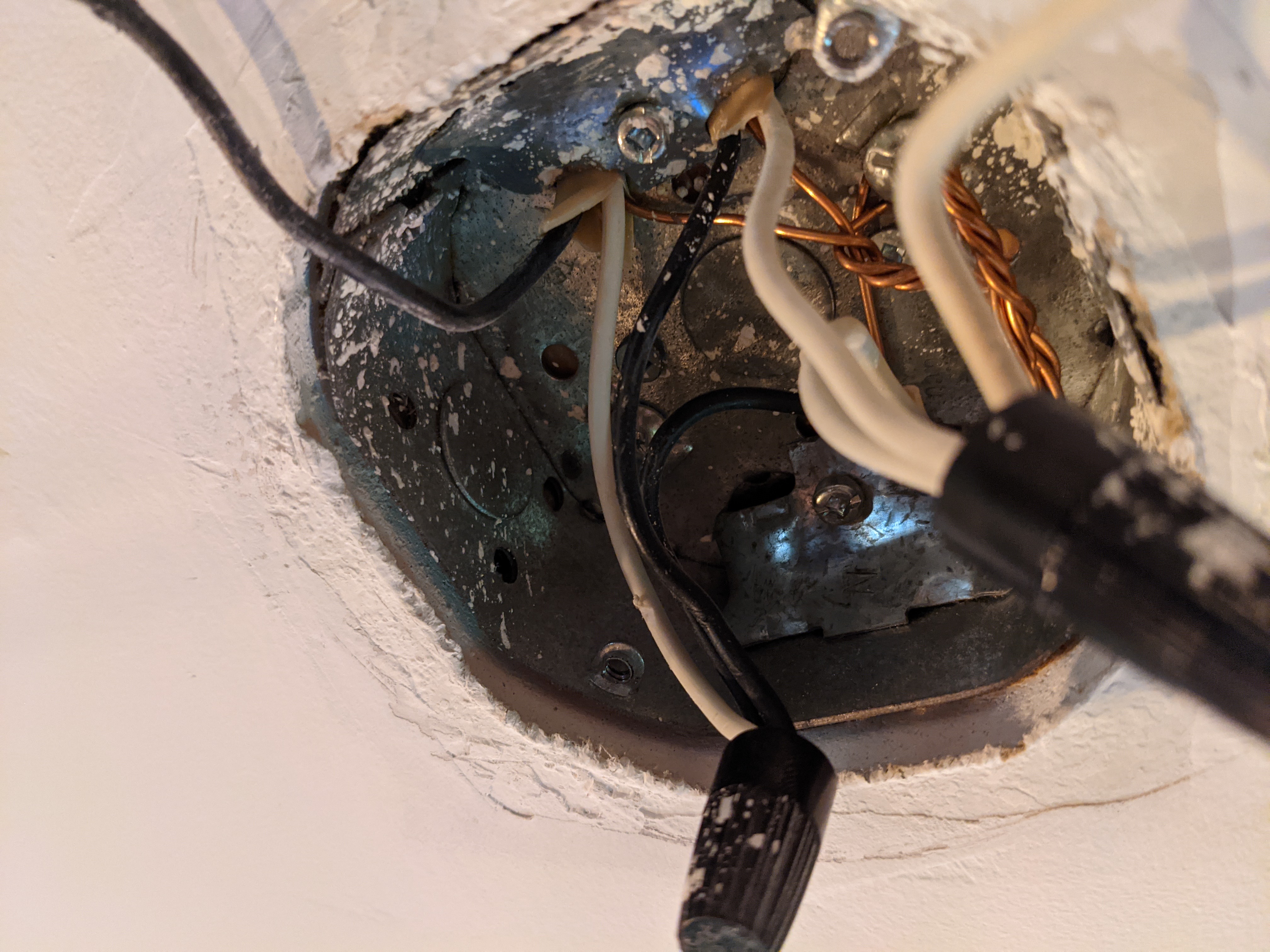
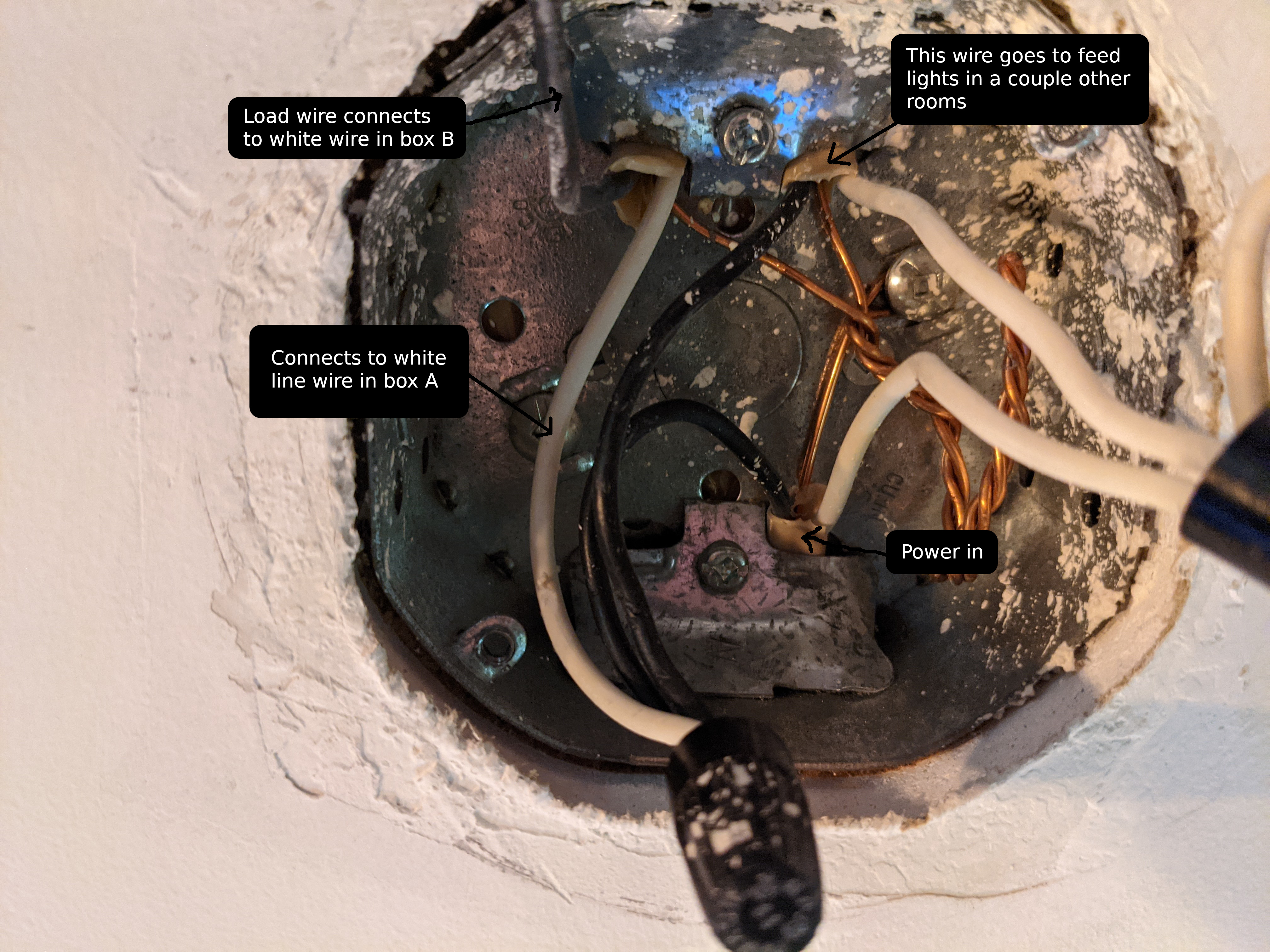
Wait I just realized I already took a couple pics the first time I had this apart. And you’re right by the way, the hot wire comes in at the light fixture box. What has me confused is that everything in there is 14/2 (so where does the 14/3 in the switch boxes come from?)
Pictures of both of your boxes with the switches pulled out so we can see all the connections AND into the box would be helpful. Your connections may be correct if you had it working, but your diagram certainly isn’t. Label the box where the power is coming in switch 1 and the other box switch 2.
One thing that jumped out at me from your post is that it was working until you tucked everything up into the box. That suggests that a connection became loose in the process. Make sure that if you use the backstab holes that the conductor is between the backing plate and the screw. A common mistake is that the conductor is placed on the wrong side and then disconnects during the tuck process. A good test is to pull firmly on the conductors to make sure they are firmly attached.
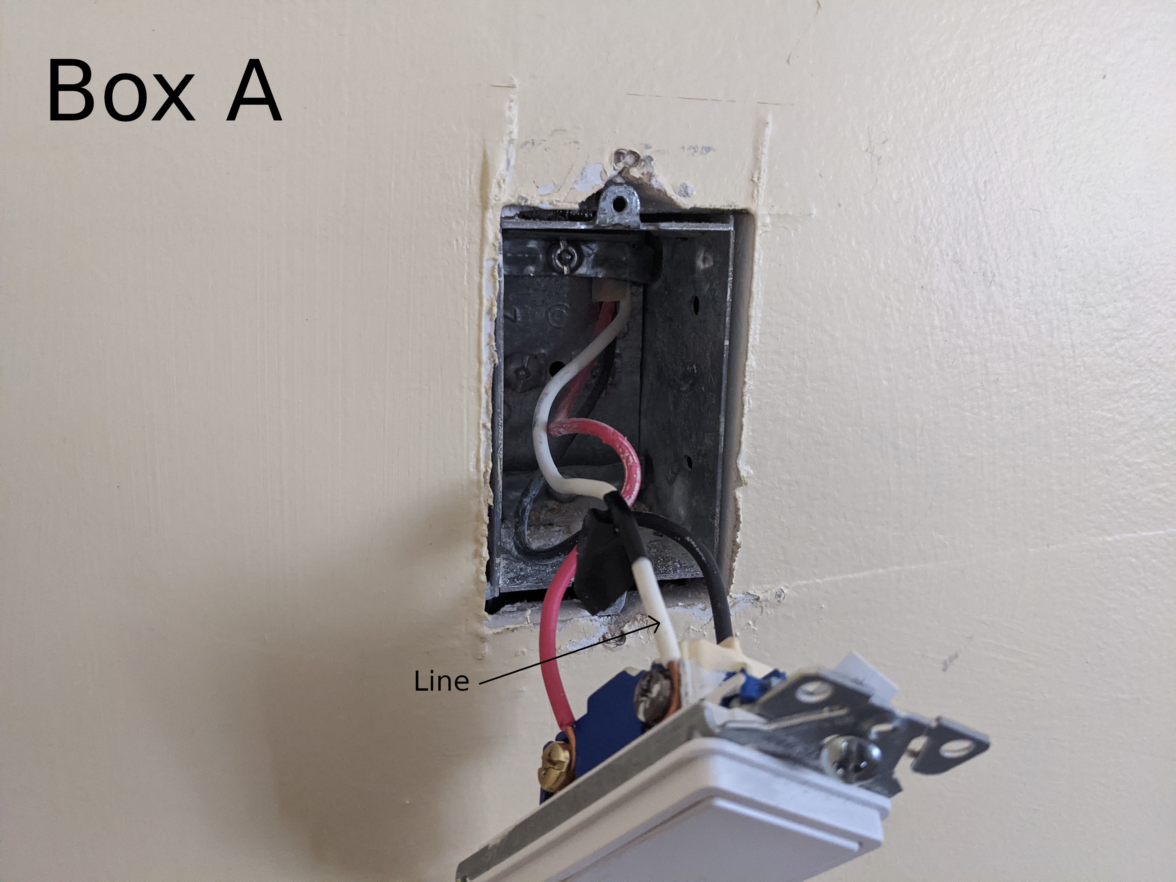
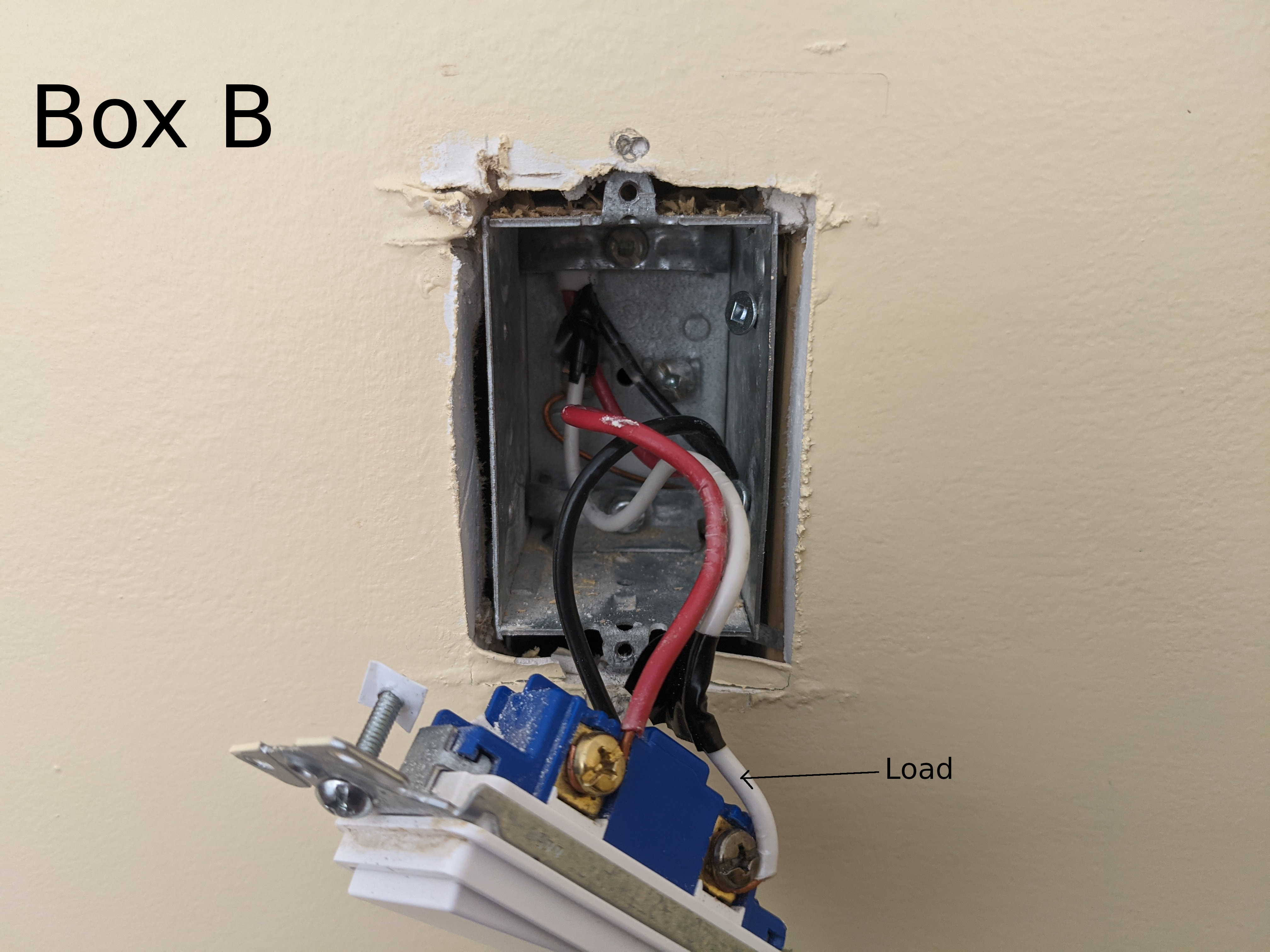
Ok, here it is. Box A - where the power comes in - corresponds to the left side in my wiring diagram above. Box B is the one on the right and has what I presume is the load wire.
I’m 100% certain the issue isn’t just a loose wire. When BOTH switches quit working I tightened up the screws and gave each wire a tug test then re-tested with the switches hanging out of the box and neither one powered up again.
Not sure what makes you say my diagrams are wrong. I believe they’re accurate.
Ummm is there another junction box or light in line? And we’re 100% sure these two switches operate the one light, correct?
I only see 1 romex in the boxes which doesn’t correlate to the light box, so that makes me wonder if there’s a JB somewhere.
Also, the pictures of the switches on my screen are a bit off. The line/load are connected to the BLK screw on the switch correct? Almost looks silver to me, but could be black too.
Yeah that’s what I was saying in the original post… Must be a junction box in the attic somewhere but I haven’t ventured up to look at it. I can get up there and trace wires around, but I had assumed that it didn’t matter since I have what I need in the switch boxes.
Yes, 100% sure those two switches only operate the one light (unless they’re connected to some device somewhere we’ve never seen or used). Line/Load are connected to the “black” screws, yes.
If you think we need to get pics of the JB, I can go monkeying around in the attic and get more pics later. I was just hoping to avoid all that (it’s a PITA lol).
Indeed I do have a multimeter. I have confirmed that the white wire in box A is the line in, and that if I tie the red and black wires together in box B, then the continuity tester beeps so they’re travellers.
I’m not really sure what else I should be looking for.
So at the light box it looks like there’s a wire in that’s providing power. 1 unswitched line out to some other fixture somewhere, and then the last wire is the power and the switched load for the light fixture.
I suppose what I’m saying is that I can go poke around and figure out exactly what wires do what at the light fixture box but I’m not sure how it helps.
That said, if you think it will help, I’m happy to go poke around with the multimeter and label each wire in the above light box pics.
Well without know the box in between, it’s hard to tell if they switch the load wire back to BLK. Because Box B Load is WHT, but the only WHT I see at the light fixture is the neutrals and the WHT that appears to go to LINE in Box A.
I guess the big question is check Box B Load (WHT w/ blk tape) and see which wire it is at the light box.
Agree with @harjms re a junction box or switch somewhere. Looking at the wiring in your light, I see a black connected to a white, which is what I would expect with a non-neutral to the switch configuration. Typically the hot is sent to the switch over the white and returned switched via the black. So there is a 2-wire leaving the light box, but only 3-wires showing up in the boxes. There has to be a box or another switch somewhere. It’s either (hopefully) going to be a j-box or another switch. I’m not suggesting you don’t know your house, but we’ve had folks discover switches that were hidden by furniture that they didn’t know that had.
Regarding your drawing, I made that comment because there isn’t a light or power feed in it, but more importantly, the Load wire on the Inovelli goes to the light. In your drawing, you have it going to the other box where it is not connected to anything. But that’s not important right now, lol. Let’s get your wiring diagnosed.
I guess the big question is check Box B Load (WHT w/ blk tape) and see which wire it is at the light box.
I just assumed that was the load wire since it was connected to the black terminal in box B… But not really sure how I’d go about testing which wire it is in the light box. I guess the only thing I could think of is just to disconnect the switches, light etc and connect the line in at the light box to what I think might be the white wire in box B, then hit the power and see if it’s got 110v? Sound reasonable? Or is there a better way to test it that I’m not thinking of?
As to the drawing, you’re right… There’s no light fixture, etc because I didn’t really know what was going on at the light (since they’re all 14/2) so I just left it out of the diagram.
Ok so we’re all on the same page then. Tonight I’ll poke around with the multimeter a bit. I suspect I’ll be taking a stroll in the attic looking for a JB sometime soon too.
There’s multiple ways of doing it. I use the ohm function of my DVM and a long wire to connect on one end and test the wire between the two ends. I’ve been bitten (not literally) before using ground, so just a habit of mine. You could use ground as a return. Using your example, I would disconnect the WHT w/ BLK tape, wrap my long wire (cat cable or green wire) on the exposed copper, reel out to the light fixture, take my leads and connect the lead to the long wire that goes back to SW B and the presumed LOAD wire in the box.
You could also connect everything like normal, turn on the light, go to switch B and disconnect the wire from the BLK COM screw. If the light goes out, verify 120VAC at the COM screw.
So that I’ve done already, and yes there’s definitely 120 on the black terminal in box B
My lord… now that you’ve said that it seems so obvious. Don’t know why I’d never thought of that. I don’t think I have any wire long enough lying around so yeah that makes sense. I’ll just ground it out and poke around in the light box. ty sir!