Scratch that…I don’t think we have enough wires here since Line/Load is in separate boxes. I’ll see if I can draw something up to reflect.
Edit: Unless we can find that JB
Scratch that…I don’t think we have enough wires here since Line/Load is in separate boxes. I’ll see if I can draw something up to reflect.
Edit: Unless we can find that JB
What is LC in your diagram? Is it possible to use a circuit breaker tracer to follow a wire in the wall?
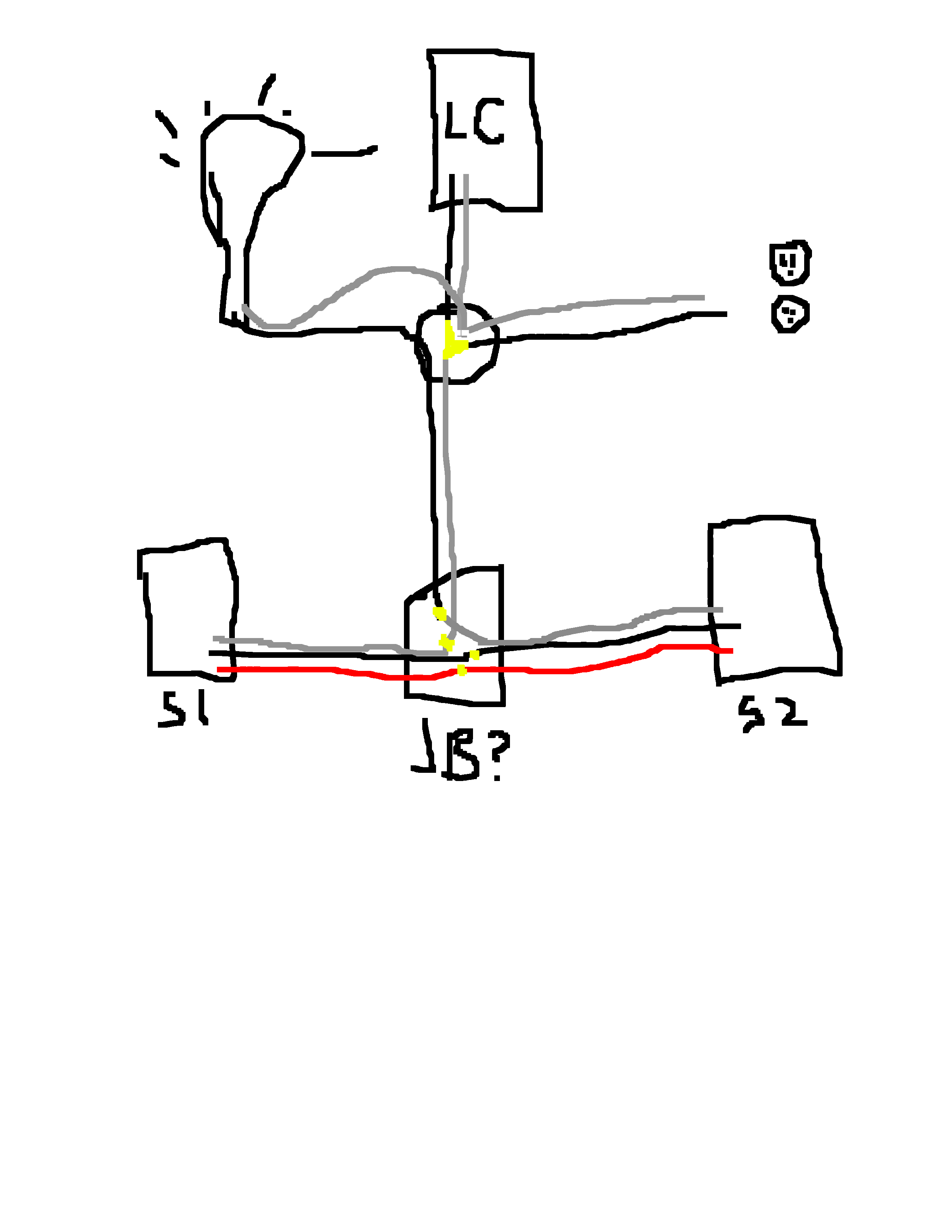
Something like this…
@stu1811 - LC = Load Center…or power panel.
So what you posted there is about what I pictured. I’m still not clear on why the way I wired it doesn’t work though.
I assume by Sw 2 you mean the aux switch? Isn’t that what I did? Maybe it’s not clear from the original diagram, but I wirenutted together the white hot, and black wires in box A to send power to box B. The load wire is already in box B so we should have everything we need there then. Line, Load, and Traveller.
Don’t know if what I’m saying and what the diagram I made originally shows is clear. I’ll take a bit of time and diagram out my proposed solution (the one i already did that didn’t work) and hopefully you guys can explain WHY it didn’t work. I’d really like to understand that before moving on.
Again, thanks for all the help lads. Much appreciated.
I think the biggest reason why is you’d need 4 wires coming from Sw1 (Inovelli) because you need line, load, traveler, and a 2nd line to go over to the aux switch.
Load has to come from Inovelli not the aux switch.
Ahh I think we’re hitting on what I don’t understand…
So the way I’d wired it before - I put the inovelli switch in box B. The aux switch was in box A.
The line from the light came into box A, so I wirenutted that together with the black traveller wire to carry power to box B. I also attached a jumper wire to power the aux switch in box A.
So in the end we have in box A: The aux switch with a line wire and a traveller attached
and box B: The inovelli with line, load, and traveller.
You said:
I feel like we’re getting close to a eureka moment for me… I think this is what I’m not understanding:
Why would you need the second line wire? With the a fore mentioned configuration power would come from the light box, to box A (Aux switch) then from there to box B (Inovelli) all with only the 3 wires I already have.
It seems like this all might be due a fundamental misunderstanding on my part on how the aux switches work…
My understanding is that they just need to have power, then they use the single traveller wire basically as a data line to tell the inovelli switch to either turn on or off the light. The aux switch is always powered right?
Am I mistaken?
Ahh I see now. Originally I was thinking Inovelli in Box A and Aux in Box B.
With that being said:
In box A you can hook up the line (wht) to the neutral port and use the second hole to connect the black over to box B. Connect red to traveler port.
In box B, connect the BLK wire from Box A to line port on Inovelli switch, red wire to traveler port and wht wire to load.
Is that how you had it wired?
Yes, that’s EXACTLY what I did. (Well except I used a jumper wire instead of second hole, but yeah, basically what you said).
Sounds like switch config at that point cuz it should’ve work. Maybe try in a single way setup first to make sure it works. Just disconnect traveler and reconfigure to parameter 22 as 0.
Ok - if nothing else it’s good to have validation that the wiring I used should work…
Hmm… I don’t think there’s any switch config that would make the LED go dark and the switch do nothing?
But I’ll try connecting one of those “dead” switches to a single pole circuit (nice and simple) like you suggest and see if it powers up tomorrow. Maybe it will. While it didn’t seem like the switch was powered I didn’t smell the “magic smoke” you usually do when electronics blow up.
Oh definitely is. It’s called Dead config.
If the dimmer is dark, try salvaging a cpu cord, cut off the C13 end, wire it to the dimmer, plug into an outlet and see if it’s really dead.
Good idea… So I just did exactly that. Both switches are properly dead. No LED lights up when I plug it in. I assume the switch doesn’t need any kind of a load to turn on if it has a neutral?
So that makes me pretty hesitant to stick ANOTHER switch in there in exactly the same configuration. 1 is a coincidence. 2 is a pattern. 3 just means I’m dumb lol. I feel like I’m just asking to throw away another $60.
So we’ve established that the wiring method is correct. Is there any scenario in which a bad dimmer bypass or (less likely) a bad aux switch would cause the inovelli switches to blow up?
Nope. With a neutral, load isn’t required. It should at least power up. Air gap switch isn’t pulled right?
Idk, 2 being bad is questionable. Maybe try the switch in a single way setup, get it working, then add the aux? All my switches have neutrals. One has a bypass with it. I haven’t had any blow up either with about 30 switches.
If no fault of your own, you could ask for a RMA.
No the air gap is definitely not pulled on either switch. Ok I’ll try wiring it up as a single pole without the aux switch to start. Hopefully I don’t kill another.
Like you say, 2 bad switches in a row is pretty questionable. I’m not sure an RMA request is reasonable at this point. I’m not convinced I haven’t done something wrong.
Just so I’m 100% clear… The dimmer bypass is there just to put a load on the switch when there’s no neutral right? So it should be wired in parallel at the light? So one end of the bypass connects to the load, and the other to the neutral? Is that correct?
Correct. You put in in line from the load to the neutral. So in your case, attach it to the BLK that was identified as Load at the light fixture. The other end of the bypass will be attached to the neutral bundle.
Ok, that’s exactly what I did.
Still a little hesitant to hook up another switch the same way now. I think I’m going to go hunting for that junction box in the attic first just to make sure everything looks like I expect it to. If that all checks out I’ll try the single pole setup using a new dimmer and a new bypass.
If that works, I’ll add in the aux again using a new switch.
And if I blow up another I’m stumped lol. Wish me luck 
Then it was never meant to be. Seriously, it may have been a fluke. Just take your time when wiring up; double check the connections.