So in the interest of not blowing up any more switches I just wanted to make sure I’ve got all my ducks in a row and that we 100% understand each other etc, etc. sooo…
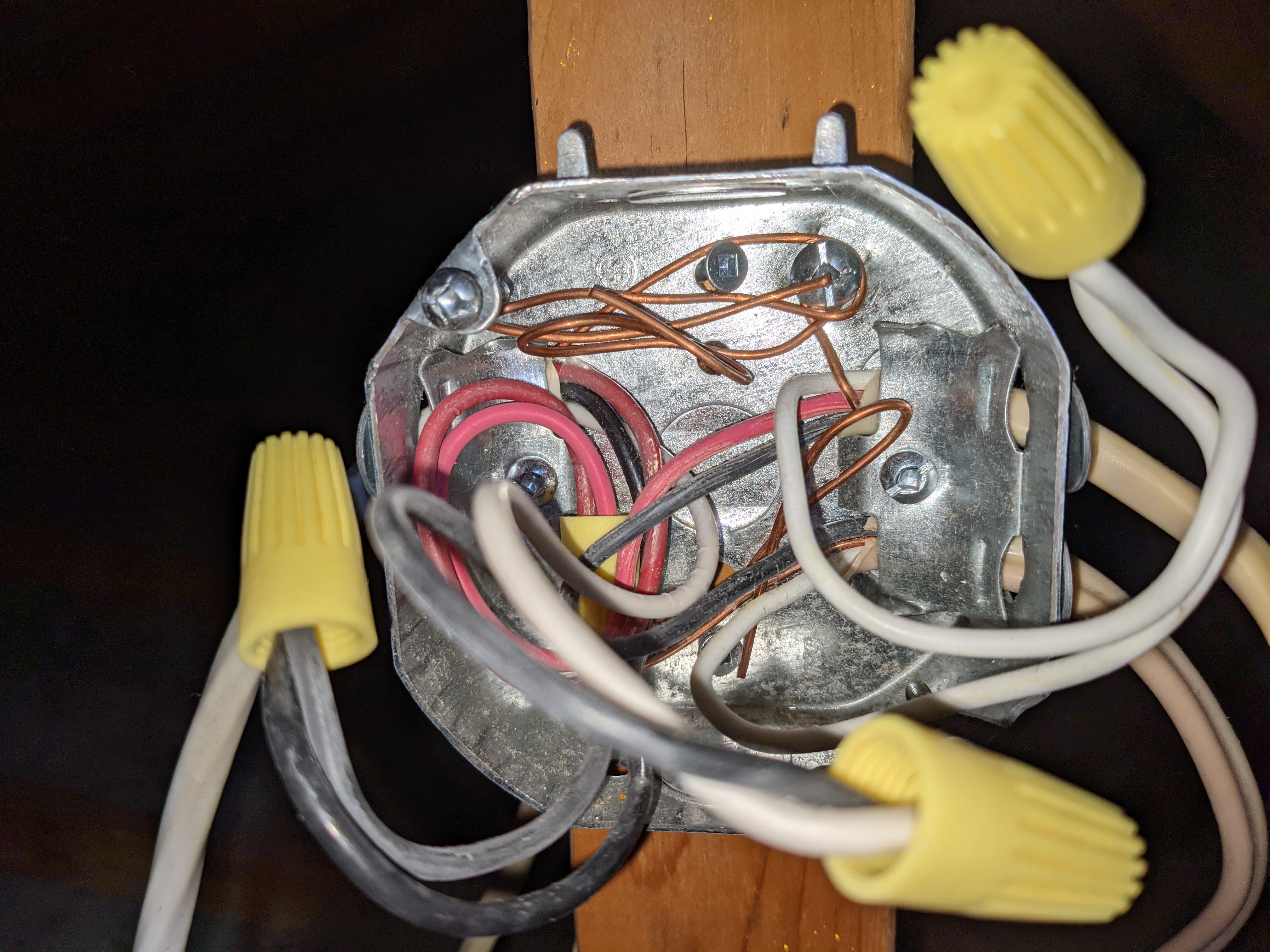
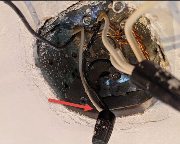
I ventured into the attic after work tonight, and found the junction box. It was pretty much what I expected to find:
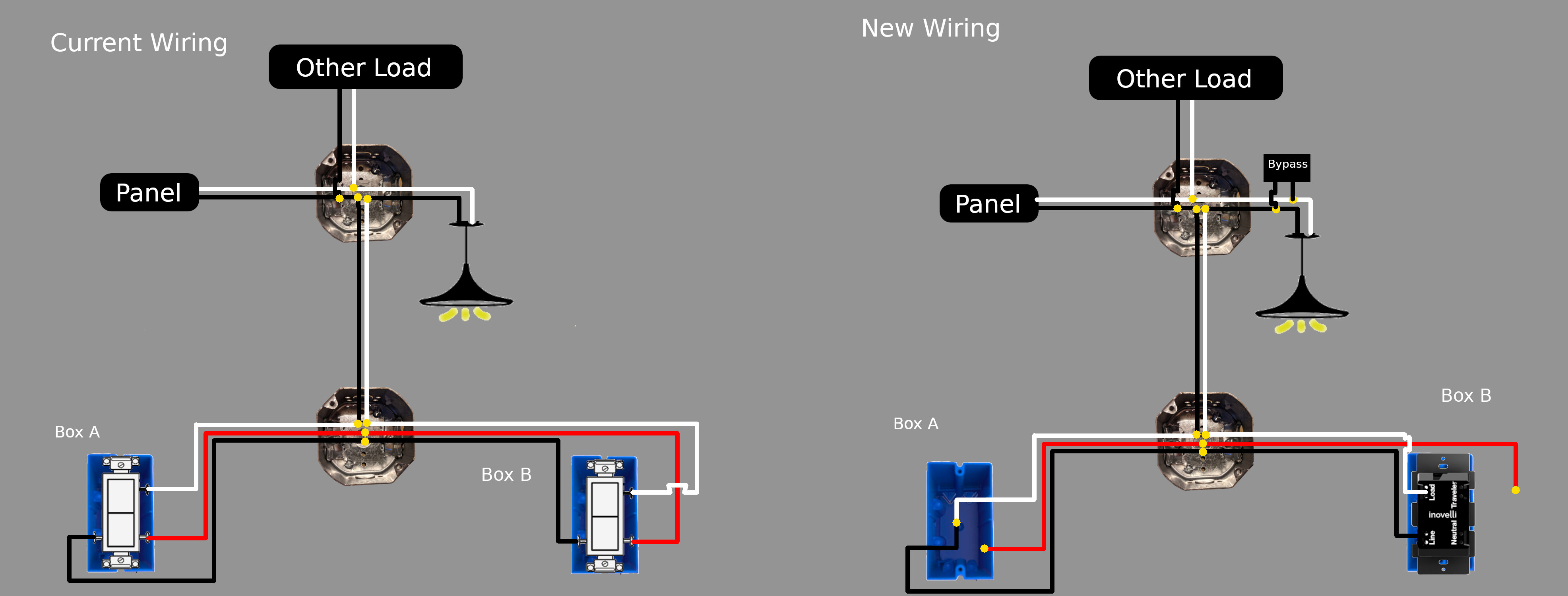
So I think your concept is correct but the wire colors in your drawing may be off. Your drawing has the hot entering the j-box on the white. Unless you’ve re-wired the light fixture, that’s not correct. If the colors in your drawing or off, that may affect the logic so I would double-check those connections. It’s a bit hard to tell without the Romex in the j-box labeled. I’d meter those conductors in the j-box as well.
Hey good catch!! I actually did the drawing before I went and looked at the junction box. The white wire in box A is definitely the hot wire, not the black (I metered it). So here’s a revised drawing to show the colors accurately:
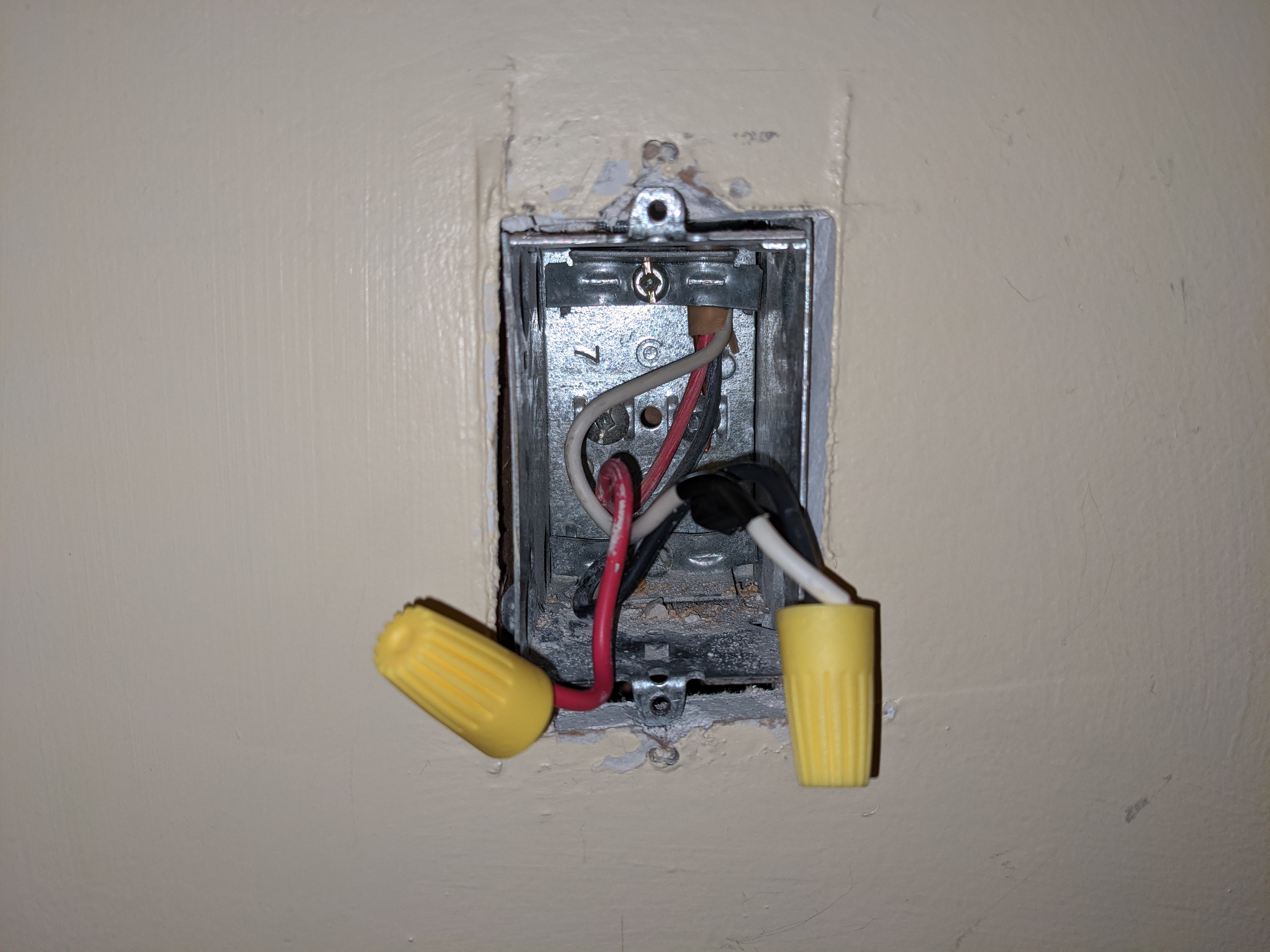
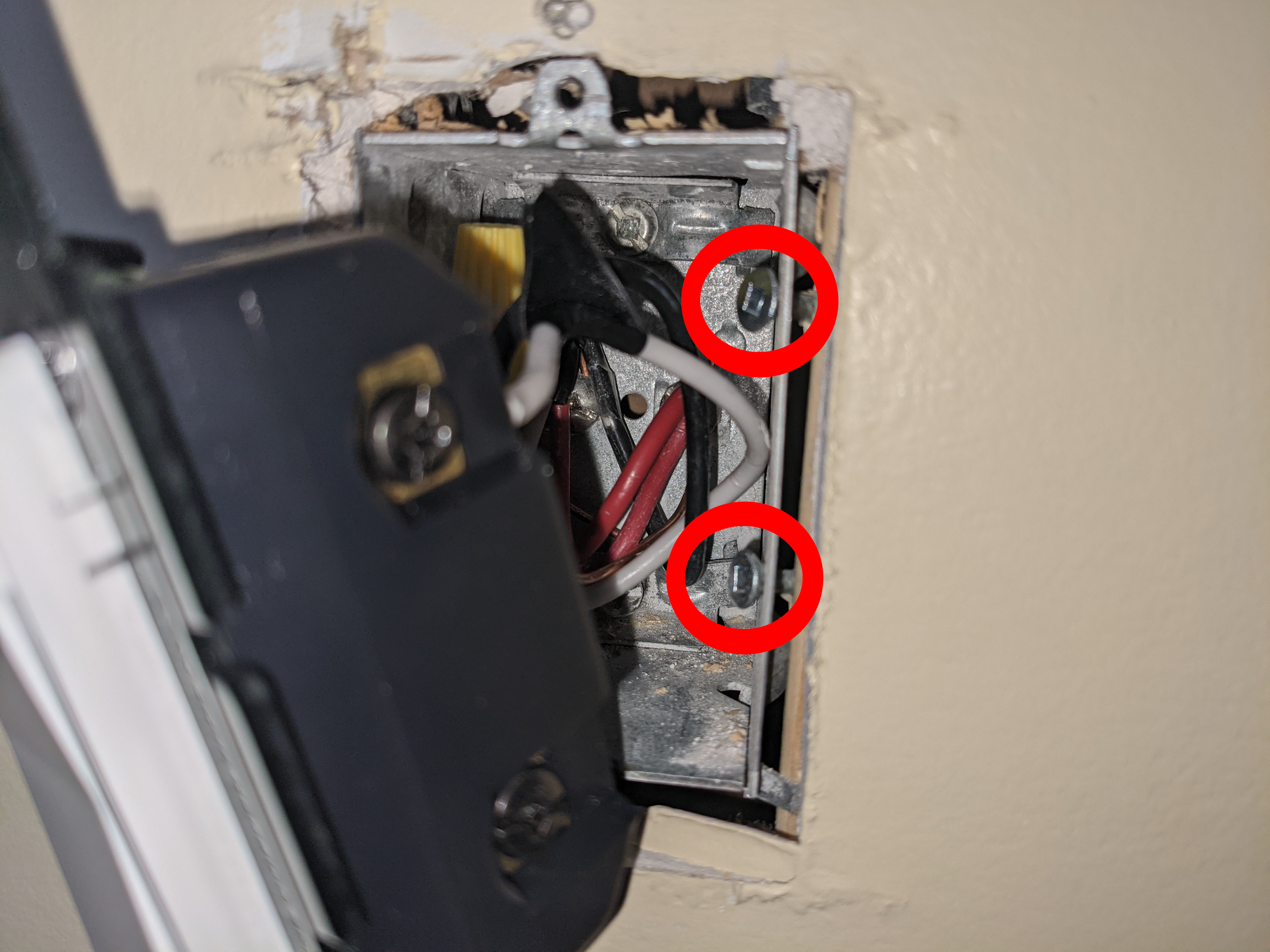
So I was still pretty hesitant to just hook everything back up the way I had it in the first place… So I took a bit of time this morning going over everything one more time before I hit the power and I noticed this:
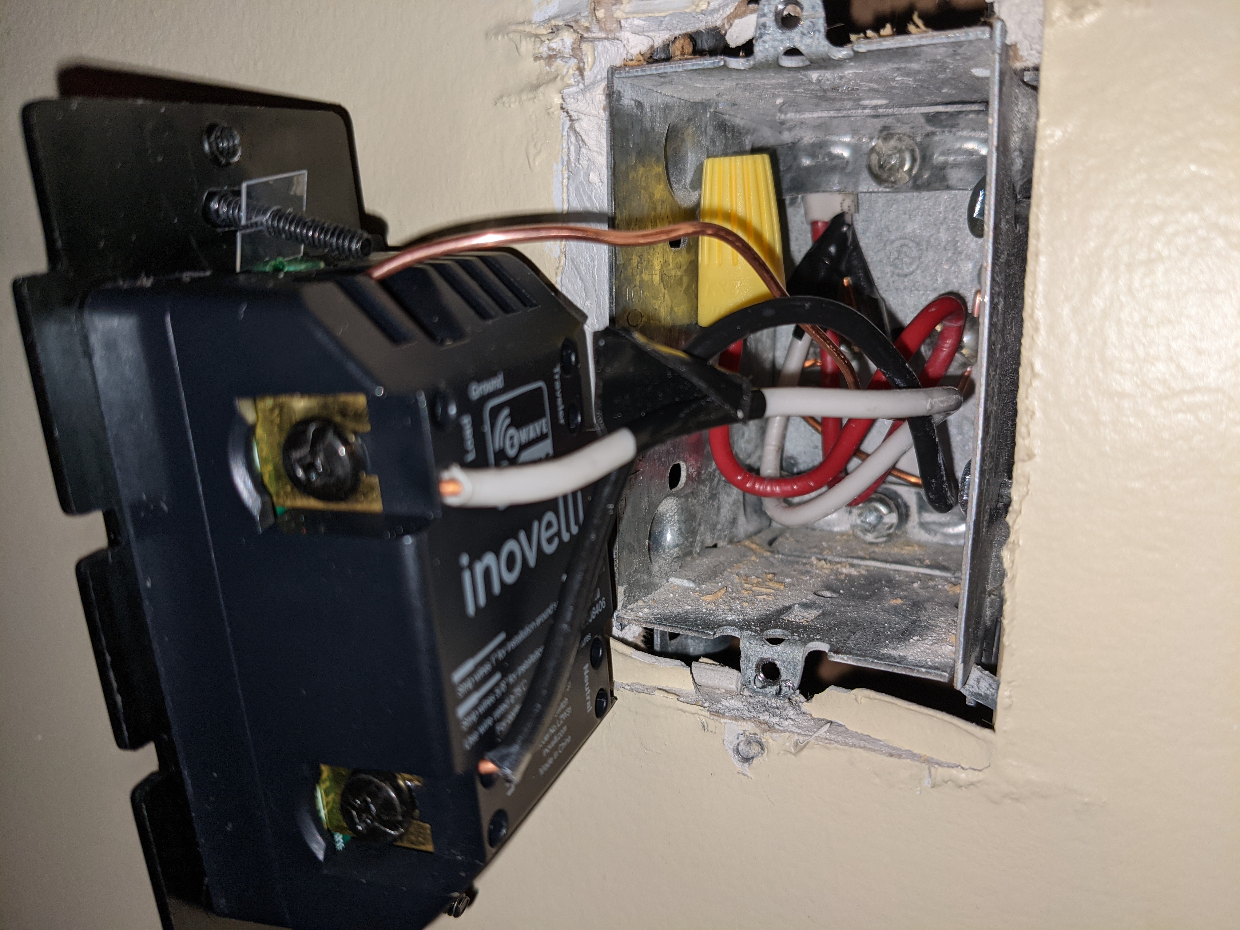
Those screws line up exactly with the line and load terminals on the switch! And totally explains why everything worked until I put everything back together the last couple times.
So after screwing them in a little more and taping the switch everything is working as expected now!
I can’t believe I missed this the first two times, but happy it’s all sorted now.
I can’t thank you guys enough for your time and patience. Even if the wiring itself wasn’t the cause of the problem, it was worth the price of admission just having you guys validate that nothing was wrong on that front. And the suggestion of using the ground as a return for continuity testing is gold. Thank you again!
Glad you got it working! I saw those but didn’t realize they stuck out that far. There are retrofit boxes that have side screw mounts, but that’s not one of them lol.
Also, an electrical tape wrap to cover the screw terminals never hurts!
Meh. It’s not a bad practice but the devil’s advocate will say that tape will decompose over time.
All the NEC says is that the energized contacts shouldn’t come into contact with anything, but doesn’t specify how. This was a practice that is/was more common with metal boxes than plastic ones.
Moreover, that box wasn’t designed to be installed that way.