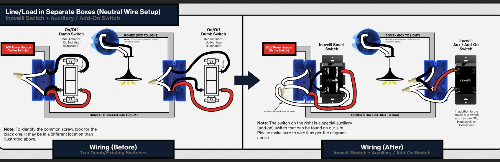
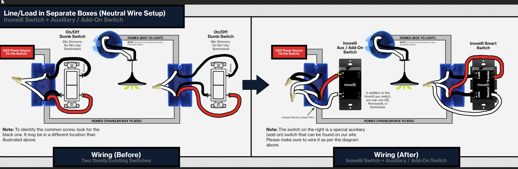
Well, it’s not what I thought it was . . and now I know why.
What I’m seeing is a line in Box 2 and a load in Box 1. I’m going to describe your wiring topology so you understand what you have. The conductor colors are not used according to common convention. While that is not wrong, it’s confusing.
The line box is Box 2. Power is fed from the black bundle to the black common screw on the switch. Inexplicably, whoever installed this chose to use the red and the white as the travelers in the 3-wire. That leaves the black in the 3-wire to send the neutral to the other box. That’s why you see that black conductor in the white neutral bundle. Not incorrect . . just . different.
The load box is Box 1. The white and black travelers from the 3-wire are attached to the two non-common screws on the switch. The load Romex (to the light) is the 2-wire. The black from the 2-wire is connected to the common screw on the switch. The neutral (which comes into that box over the black) is connected to the white from the 2-wire, which explains why you see a white and black bundled there. Not incorrect . . just . . different.
You should confirm the connections I have described before proceeding further. If they are correct, I’d say you could put the Inovelli in either box so long as you are mating it with an Aux switch. Either of the following diagrams should work. Box 1 is on the right.