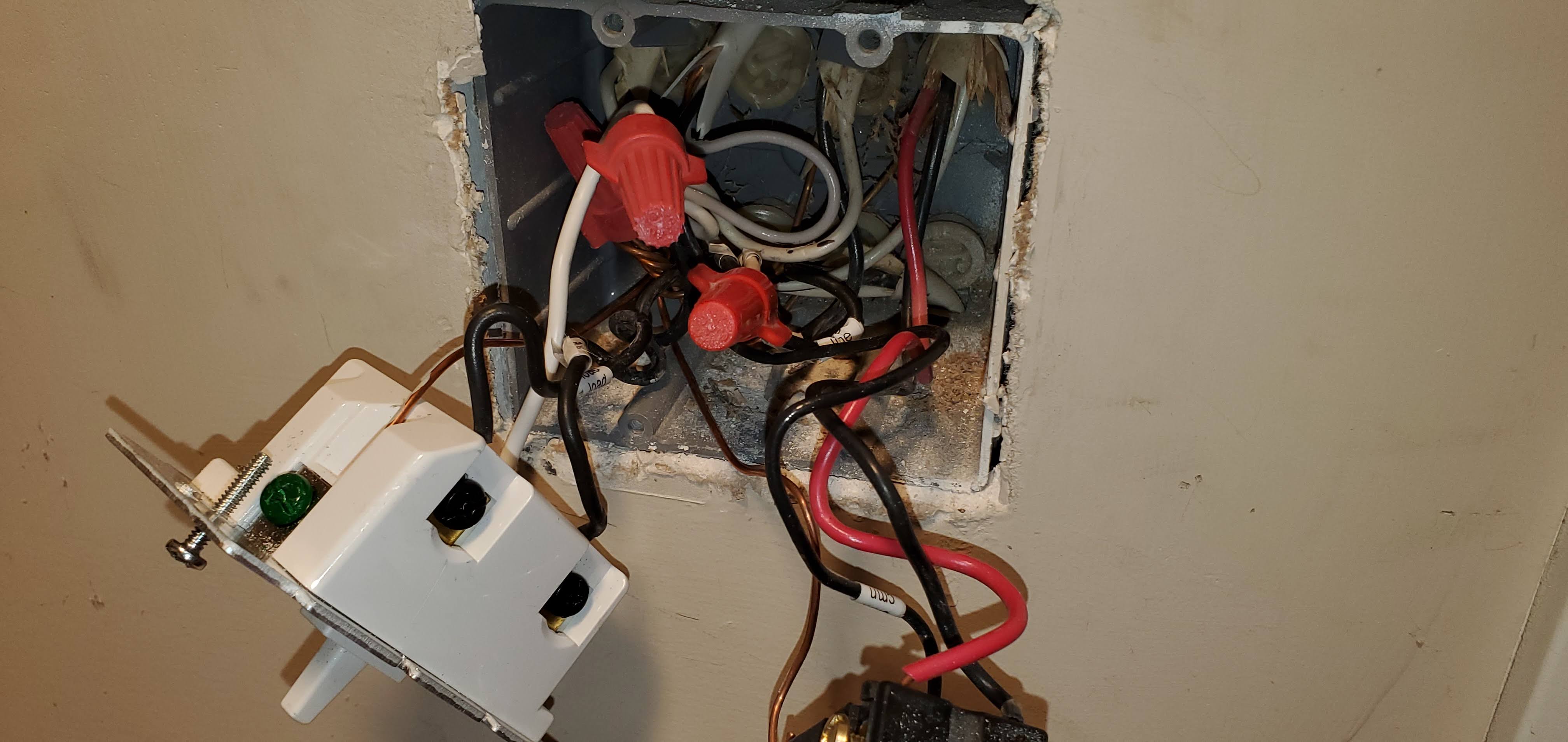
Thanks for the video. That helps confirm your configuration. Here is what you have.
This is a typical line and load in the 2-gang box we’ve been focusing on. The Inovelli will go here, and you have a neutral.
Just so you understand how it’s wired now, the hot for this switch leg originates in the box at the black bundle, The hot is sent over the white conductor of the 3-wire to the other switch. At the other switch, that white is connected to the black (common) terminal. The switched hot is then returned back to the other switch via one of the two travelers (black or red) depending on the position of that far switch.
The 2-gang box switch then sends the hot to the light(s) via the black and white 2-wire in that box. That black is connected to the common terminal of that switch and the white is bundled with a neutral.
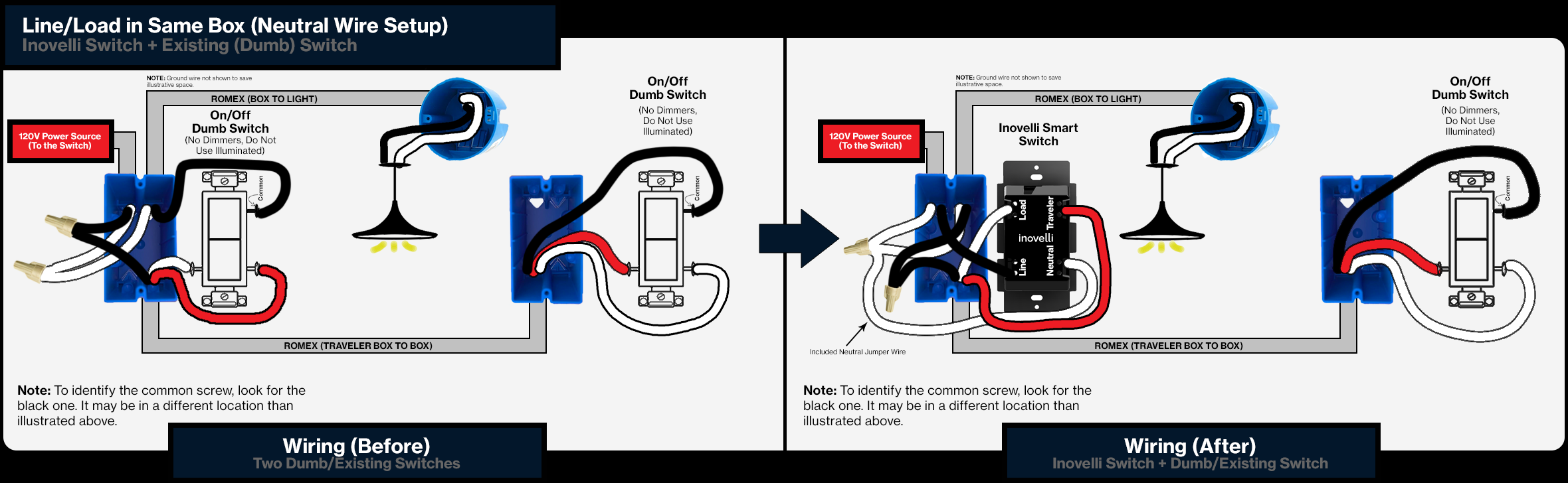
So what you have is this. The only difference in the “before” picture is that in your case, the hot is sent to the far box via the white, whereas in the Inovelli diagram, the hot is sent to the far box via the white. So in both the before and after, you have to mentally swap the black and white conductors of the 3-wire.
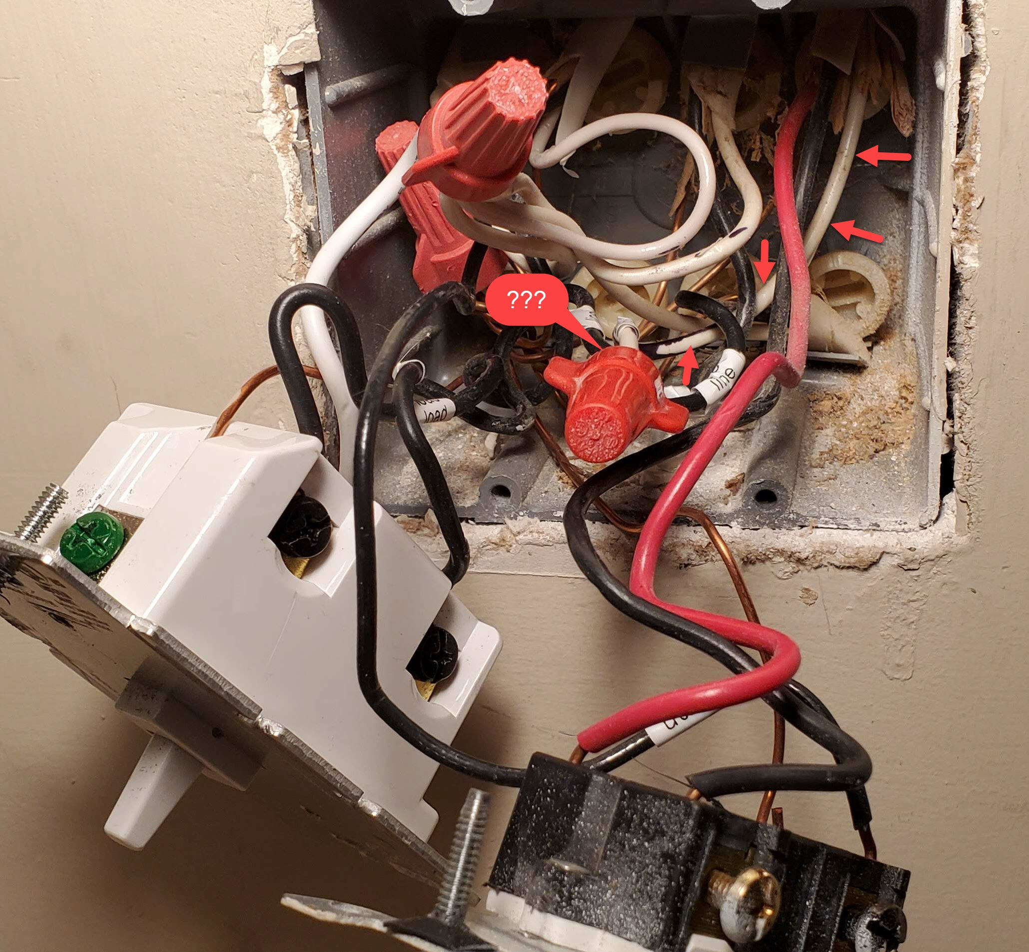
So the Inovelli gets wired like this:
Pigtail a white wire onto that bundle of all whites and connect to the Neutral terminal on the Inovelli.
Pigtail a black from the black hot bundle to the Line terminal on the Inovelli. Remove the white from the 3-wire from that bundle.
Connect the red and black from the 3-wire to the Load and Traveler terminals. It shouldn’t matter which goes to which.
Connect the black from the 2-wire going to the light and wire-nut it with the white in the three wire.
You’re following the graphic above, but swapping the black and white of the 3-wire. Or if it’s easier, wire exactly as in the graphic, but you have to swap the connections to the switch at the far box.
 Might wind up just being a non-neutral 3-way, which would also be ok. There’s plenty of load (4x 8’ fluorescent lights).