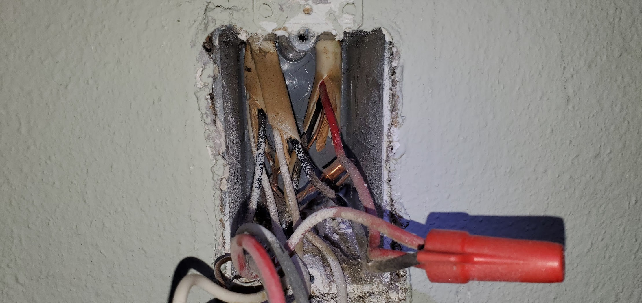
The last switch to tackle in my house is in a bedroom. I cracked open the boxes today and was greeted with wiring that hasn’t been touched in almost 40 years.
Despite no red wire in sight this is still just a 3-way line/load same box with neutral wiring, correct? They just didn’t use a three conductor wire and pulled an extra two conductor wire to get the “red”?
Is there any configuration I can do where the Inovelli switch is at the far end? I want the ability to run scenes and see the status light from that location, not the near location. From reading around it sounds like I would do the “3-Way Installation (Using Two Inovelli Switches)” version with the limitations inherent in that (which I don’t care about provided I can control scenes and the LED light at the far end). Is there another method that doesn’t require buying two Inovelli switches?
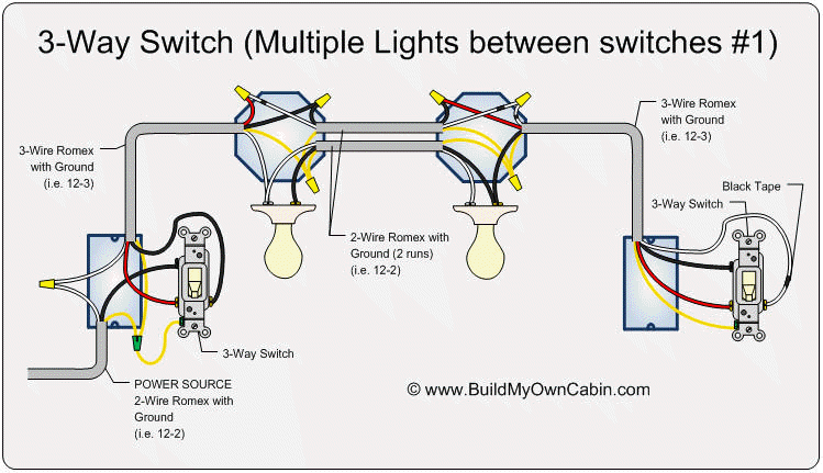
From viewing video alone, it looks like you have a line in the near box and lights between the switches. (I think Inovelli calls this load in both boxes or something like that.) You don’t have line/load in the same box, but it does appear you have a neutral in the near box. If that’s the case, it looks like this, with the exception that two 2-wire Romex are used with one white conductor unused.
If you can get a the lights, I would look in the boxes to confirm what you have. If it’s as you think, you are fortunate that you have an unused conductor. I think that with re-wiring, you can send a hot and neutral to the far box and place the Inovelli there and use a dumb switch at the near box. Basically, you’d be flip-flopping the two devices and moving the hot. This is off the top of my head. You’d have to draw it out to make sense of that configuration.
You could also probably a little more easily send the hot and neutral to the far box and use an Aux in the near box. Since you already have a neutral in the near box, you would just need one conductor between the two switches to communicate. As before, this is off the top of my head. You’d have to draw it out to make sense of that configuration.
If you start moving things around, make sure your original configuration is well documented. Tagging the wires since you are probably using two 2-wires is a good idea.
The light this controls is just an overhead fixture in the bedroom so it’s easy enough to get up on a ladder and take it apart to see what wires are in it. Would love to send the hot and neutral to the far box and use an aux in the near box.
I’ll try and get up there tonight and draw this out on paper plus take some more video.
Any suggestions for testing with a multimeter I can/should do when I have the light apart to trace things? Or will it be obvious enough just looking at the wires in the box and sketching things out.
See if both Romex are there and note the connections.
I would expect that the two travelers are going to be in one 2-wire. You can test between there and the neutral (white attached to the light) for a switched hot. The hot should alternate between the black and the white from the same Romex as you switch the switches back and forth. You may need to separate them to get the test to work properly, finding the one incoming from the switch supplying power.
Make a note of all the connections as it gets confusing without a red.
Oh it’s plenty confusing for me even with a red Luckily I have a label printer that can print wire labels so I’ll just print out a bunch of numbers, wrap it around each wire, and label the matching connection points with a Sharpie or something.
Well for once in my life a box was simple. Took the light down and… there’s exactly one 2-wire in the box. Black to black on the fixture, white to white on the fixture, and ground. Nothing else.
Given that I only have two wires in the fixture, and three wires at the far switch, isn’t this just this setup?
Yeah, uh, no. You have the equivalent of one 3-wire at each box, with power starting at the near box. The only way I know to wire that configuration is to wire the lights in the middle as in the diagram I posted.
If you think about the diagram you posted, and you consider for argument’s sake that one of the near box 2-wires is going to the light, then that only leaves on other 2-wire leaving the box. But in the diagram you posted, you need a 3-wire going to the other switch.
Is that bundle of blacks that you referred to in the near box video a constant hot?
I have been trying to figure this out for awhile now. Everytime I think I figured it out, I see something that doesn’t work. There are 2 things that confuse me and seem to conflict with your setup. #1 The 2 wire romex in the light. #2 The group of black wires wire nutted together. I am guessing these are hot from the breaker.
Is there any configuration I can do where the Inovelli switch is at the far end?
I am not 100% sure about this, but I think you need the neutral wire for the notifications to work. which would mean ( under most scenarios) this wouldn’t work. Maybe Bry knows.
I wanted to do something similar with a 4 way and put the Inovelli switch at the end. But this is what Nathan, CSO of Inovelli told me.
“To make a long story short, yes, you do have to wire the smart switch where the line comes in. The login in the switch requires the power to be there to make the wiring work correctly.”
That might answer one of your questions, but I know it doesn’t help figuring out your wiring schematic
I’ll have to open the box tomorrow and test it to see.
But I’m confident there’s only two wires coming into the light fixture. I printed out a ton of labels to mark everything and test… only to find a ceiling box with one black, one white, and a ground. There were exactly two wire nuts in the box, connecting the incoming Romex to the light fixture. Nothing else.
That light isn’t below an attic or anything where you can get at the back side of the box, is it? I’m wondering if there might be a junction box somewhere that is feeding the single 2-wire.
Are there any 3 wire romex in any of the boxes or are they all 2 wire romex?
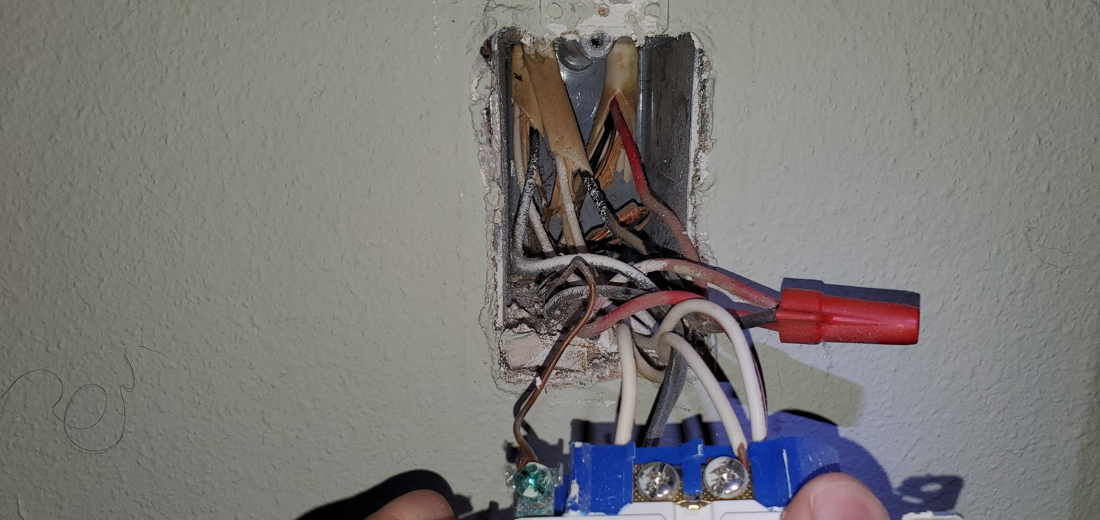
It looks like the far box has 2 romex coming in with 2 wires each. That would explain why the one neutral is capped.
@Bry Yes, it’s below an attic, and yes, it’s accessible… through 2’ of blown in insulation I’ve done it before and it’s not fun. If I have to I will, but first I’m going to look at the main box again.
@Tccshenkes Correct, there is no 3-wire Romex anywhere, and yes, the far box has 2x two-wire Romex coming in with one wire capped. I believe they just ran a second Romex to get the third wire to the far box because they didn’t have any 3-wire lying around/it was the end of the job/they had scrap 2-wire/whatever. It wouldn’t be the first time I’ve found weird stuff in this house. I should be able to confirm this by looking at the near box again.
I have the new video to show, and I just realized… I checked the overhead light for the other wires but that’s not what’s on the 3-way. The bedside light is. I need to take out the receptacle that’s split, one outlet switched the other constant. I bet if I open it I’ll see a mess of wires that look like what @Bry suspects, with the “light” in the middle. The far switch is about three feet above the receptacle it controls.
No wonder none of this makes any sense.
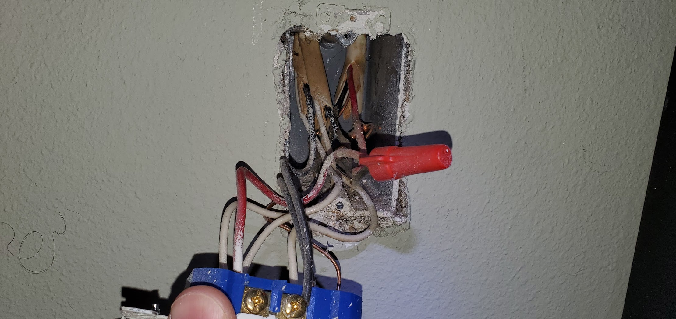
Anyway, for the near switch, it’s wired like this:
Bottom right black screw: Black pigtail into a bundle of other black wires. The only black wire that doesn’t go into the bundle is off the other 2-way switch in the box that controls the overhead light. Top left screw: White wire Top right screw: Black wire
The top left and top right screw wires are the same piece of Romex and leave the box together.
But it would have been a better story if Neil had gone into the attic first, lol.
@neile Glad you figured it out. I think you’re going to have to do this with an Aux in the near box. Confirm the receptacle first and then I’ll give you my thoughts.
So that receptacle is split. Are both the top and bottom switched? Which are switched?
a) just the one with the red
b) just the one with the blacks
c) both
And just to save time, are you sure? Look again, please.
ps. I watched the video and I know you said the top (red) was switch and the bottom isn’t. Once again, that’s not making sense, yet. A red 3-wire would normally be used for a split receptacle with the red carrying the switched hot.
I keep an alarm clock plugged into the bottom and a light plugged into the top. When I moved the nightstand out of the way I unplugged the clock but explicitly left the light plugged in so I wouldn’t get confused about which outlet did what.
To make 100000% sure I just went in there and flipped the switch on and off. The light plugged into the top goes on/off. The clock plugged into the bottom stays on.
And just to save time, are you sure? Look again, please.

 Luckily I have a label printer that can print wire labels so I’ll just print out a bunch of numbers, wrap it around each wire, and label the matching connection points with a Sharpie or something.
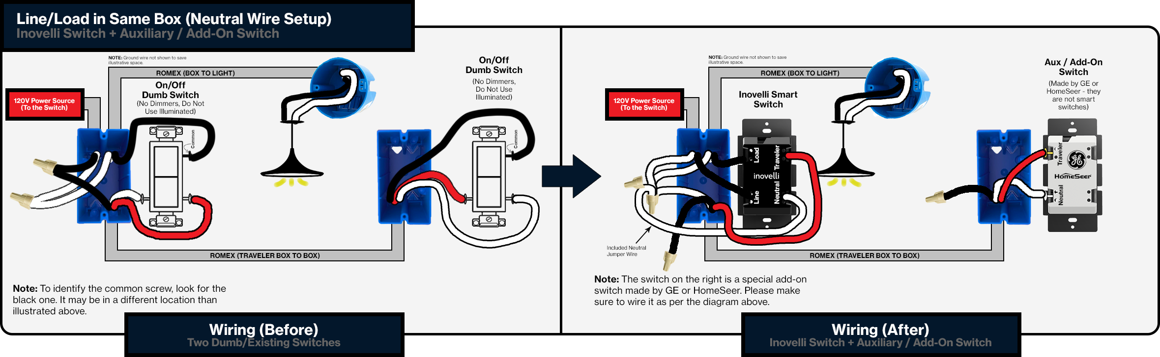
 I’ve done it before and it’s not fun. If I have to I will, but first I’m going to look at the main box again.
 I need to take out the receptacle that’s split, one outlet switched the other constant. I bet if I open it I’ll see a mess of wires that look like what