Hi Everyone, this is my first post.
I’m a big fan of the red series switches, and I’d like to order more, but I need some help before I order my next batch.
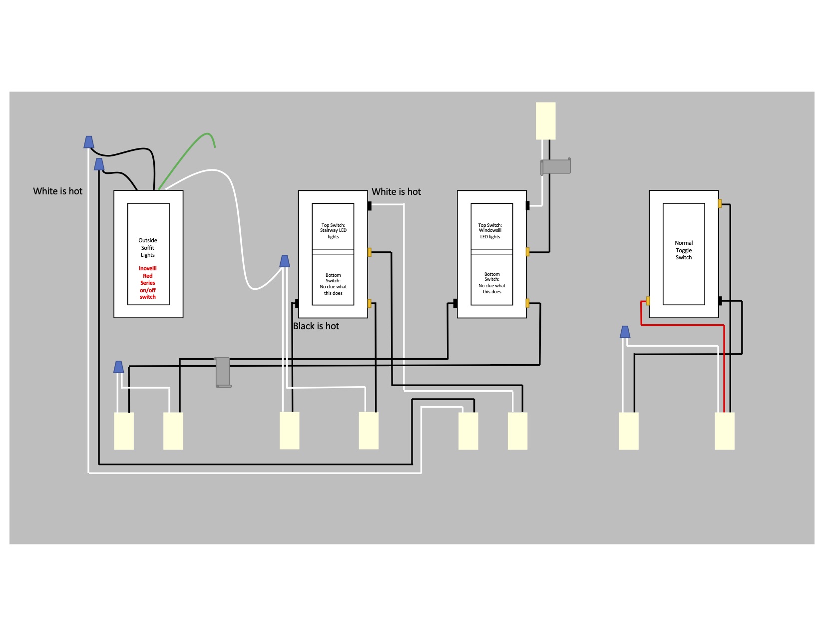
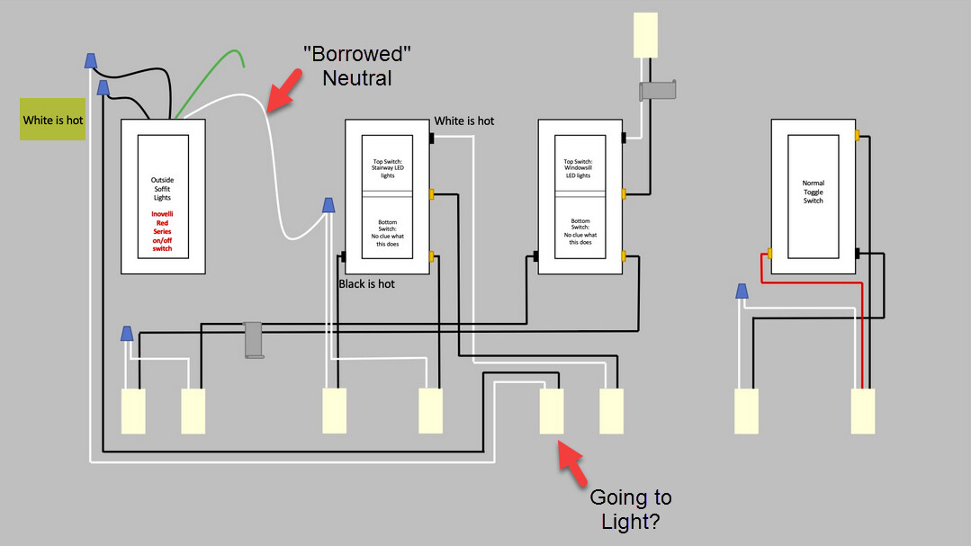
I have a 4 gang box near my front door. I have attached a wiring diagram that I made myself (at this point, you’ll probably be able to tell I’m not an electrician!)
The first three switches are on their own circuit, and the far right switch is part of a 3-way on a separate circuit.
I would like to replace the leviton timer, and the two combo switches. The one problem I’m having is that the upper buttons on the 2 combination switches turn lights on and off, but I have no idea what the bottom half of each combo switch does! We have been living in this house for 5 months, and we can’t figure out what the bottom half of the two middle switches do!
So I guess I need to figure out the following:
how can i figure out what the bottom half of those combo switches do
if they do nothing, how do I close them off so they aren’t an issue
how would I wire in three red series switches to replace the leviton timer and the two combos?
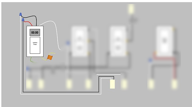
Yikes . . . How confident are you that the timer connections are drawn correctly?
I blurred out most of your drawing to just focus upon the timer. That looks like power is coming from the light via the 2-wire. But the Leviton needs a neutral, so they grabbed one in the box. The Leviton’s black lead is the incoming hot, the red lead is the outgoing (load) switched hot and the white goes to a neutral. But there has to be a hot on that circuit in that box so I’m not sure why they took a hot coming from the light unless it was wired that way originally.
Based on your drawing, I’m guessing you have Romex so you can use a meter to test between conductors and the bare copper ground for voltage. Disconnect the white/black connection on the timer and test the white on that 2-wire for a constant hot.
Bry,
First - thank you for getting back to me so quickly. This is my first post…like…ANYWHERE, so I really appreciate it.
I am pretty confident that the timer wires are correct…and I will double/triple check and update the drawing if I need to.
Just to make sure you understand what I’ve drawn from the timer:
the green wire is grounded - so that’s ok
the red/orange wire with the flag on it is dangling in the box unused.
I will open this box again and test the wires tomorrow and then write back to you.
THANK YOU.
JP
Have you checked whether the bottom half of the switches may control an outlet? Sometimes 1/2 of the outlet is controlled by a switch, so make sure you check both outlets. Is it possible they control outside lighting?
The I just tested the black wire going to the leviton timer (the one connected to the red) and the multimeter was showing numbers between 120 and 175 (back and forth - I’m writing in as much detail as I can).
Then I tested the white wire going to the leviton timer (connected to the black) and the multimeter showed a lower number, albeit not exactly 0.
Snyderr - if those lower parts of the combo switch are connected to outlets, we haven’t found any that seem to be connected. I’ve run around with an outlet tester and an electric razor (don’t ask) and haven’t found anything! There’s another one of these switches in another part of the house, and it also seems to do nothing.
The two tops of the combo switches control stair lighting (LEDs) and window lighting (LEDs) around the house (LEDs). The leviton timer controls soffit lighting outside (looks nice at night).
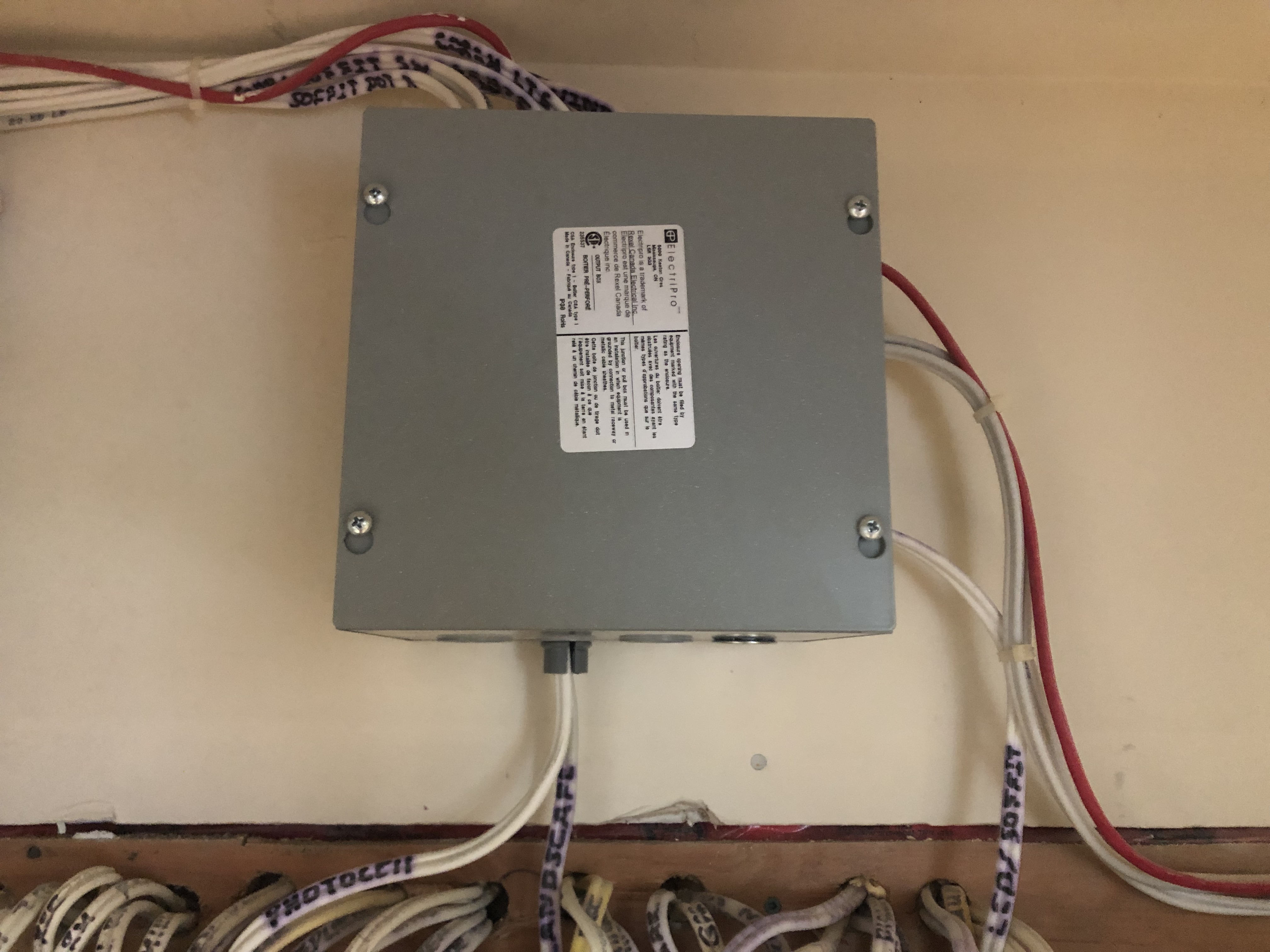
When I flip the power to test this circuit, there is an audible noise coming from a box situated above the breaker panel (I’m flipping a relay of some sort when cycle the breaker). Going into this box is a wire labelled ‘PHOTOCELL’ - if there is a photocell in our house, we have yet to find it. There’s also a wire coming into the panel that says ‘LANDSCAPE’…and we have NO landscape lighting that I have found.
I’ve included a picture of this box (all the wires at the bottom of the pic are headed into our breaker panel which is sort of mounted horizontally below this box). The noise is coming from this box. I’m including this because you’ll obviously know if this is relevant or not.
Have you opened the box to see the inner wiring? It sounds like there may be a transformer that controls low voltage landscape lighting. Sometimes builders add these things for future expansion, which makes life easier, but since the previous owner didn’t leave the lighting, or maybe never had it, it’s hard to track down what it controls. I suspect the photocell is for outdoor lighting… maybe a lamp post or garage lighting. You should look around the perimeter of your house or under a deck to see if there are any outdoor connections, outlets, or switches. Opening the box may shed some light on it as well…no pun intended.
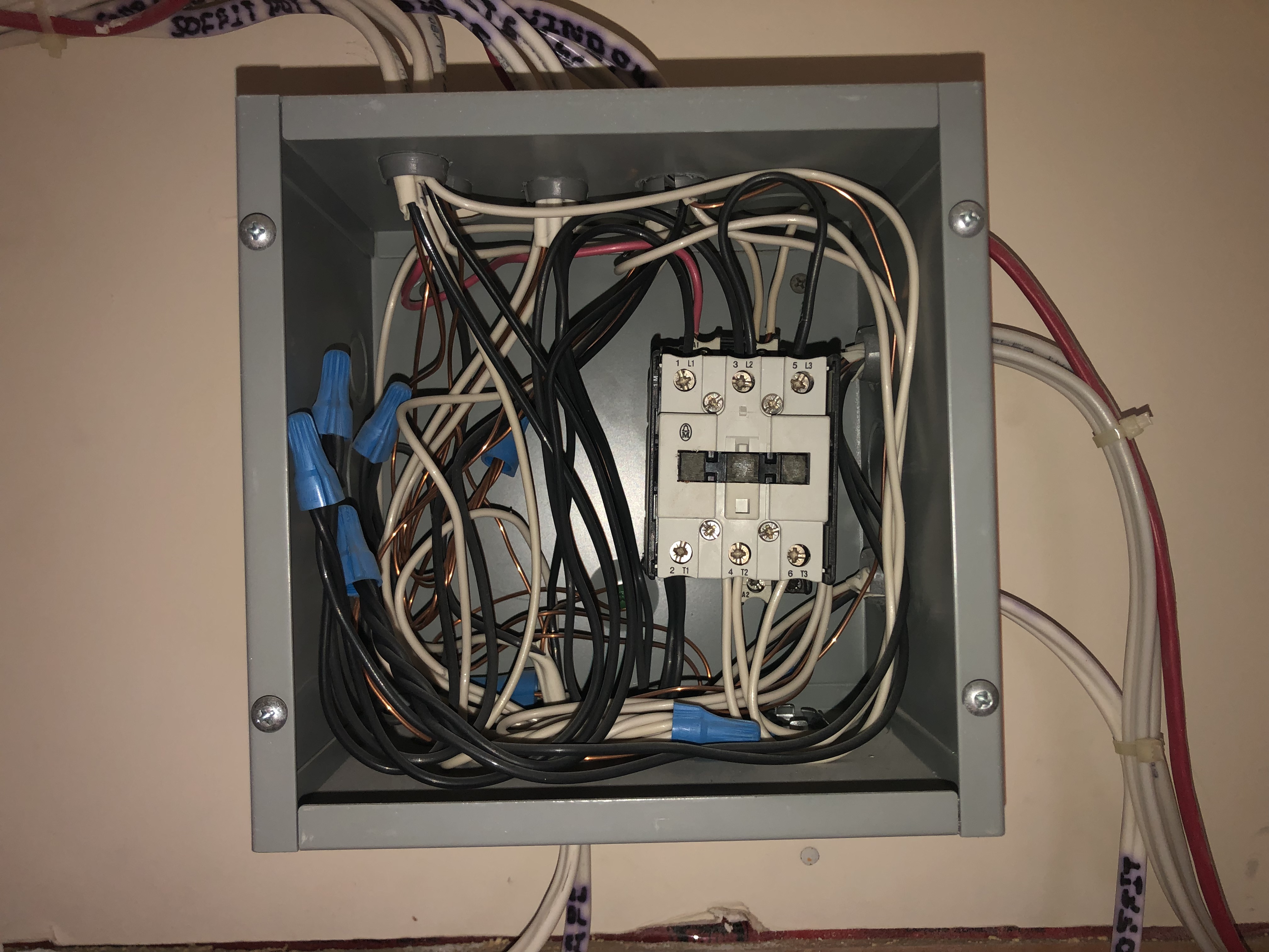
Snyderr - I took a picture of what’s in that box. I don’t know if I’m worse of now than before…ugh.
Again, if there is landscape lighting or a lamp post with lighting, we have yet to find it! We don’t have a deck (flat patio stones), but we do have outdoor receptacles/outlets. All seem to be working without being tied to these combo switches. Garage works perfectly fine on its own (with an inovelli switch I might add!).
Let me know your thoughts. If at any point you feel I should get an electrician to visit, feel free to let me know that.
Unfortunately it’s hard to discern any wiring details from the picture. It appears to be a multi-tap transformer but without measuring voltages it’s hard to determine what may be attached. Is the 4-gang box wall open to be able to determine where the cables run? It looks like the electrician was very studious in labeling the cables. At this point, you could turn the circuits off and try to get a toner to trace the line.
Do you have any contact info for the seller you purchased from? It may be beneficial to see if they can tell you.
Otherwise, if you are not comfortable poking and prodding, I would recommend asking an electrician to trace the circuit. You’ve obviously checked all of the visible elements, so it may be something that is hidden, such as attic circuits, landscape boxes that are hidden behind bushes or in the ground, or something else. Sorry I couldn’t help you more.
I agree that an electrician is warranted. The box is simply a junction box used for a variety of purposes, so it’s generic. That looks like a lighting controller inside but I don’t recognize it. I suspect that at least at one point, you had exterior lighting, landscape, wall and soffit lights that were controlled via a photocell.
Whether any of this is related to that four gang box remains to be seen. But the fact that you have switches you can’t find what they operate combined with the fact you have a switch loop for the time light that most would think should have a hot originating in that box really warrants a close look by an electrician.
If the electrician has questions about wiring the smart switches once he/she figures everything out, we can jump back in. Smart switches are new territory for some electricians, so we’ll be glad to help.
By the way, Bry - in order for me to shut the power to the leviton timer and two combos in the 4 gang box, i trip the breaker this box appears to be attached to (so must be related somehow). I’ll see if I can get an electrician to figure this all out.
Bry, I’m going to get an electrician in here soon, but I had a thought over the weekend, and I thought I’d run it by you:
Let’s say that current Leviton Timer was previously a photocell (like a Leviton IPS06-1LW) which controlled three things:
Soffit lights
Window lights
Stairway lights
All three of these have once thing in common: all used only at night.
Let’s also say that photocell switch SUCKED and they replaced it.
So now, with the current set up, the leviton timer controls ONLY the soffit lights (on a timer obviously) and the two combo switches in the middle control the window lights and stairway lights manually - but using the top halfs only.
Would there have been any use for the unknown wires if there was a photocell(s) in this box originally? Let’s say those combo switches were changed around the same time as the photocell swap. What are your thoughts on this, or do you think I’m barking up the wrong tree.
That’s a tough question, but my sense is the two are unrelated. The photocell issue is simple. The previous owner maybe didn’t like the photocell because they didn’t want the lights on all night, or didn’t like the lights coming on during dark days. So you wire around the photocell to eliminate it and replace what was probably a simple single pole switch with the timer.
Regarding the bottom half of the switches and the accompanying Romexes . . . The wiring in the Jbox that you posted a picture of looks professionally done to me. I’d look at the descriptions on the Romex by that panel and see if you are “missing” anything. It’s possible those switches once controlled something that’s been removed. It’s also possible that those switches are future-proofing for things to be added down the road. Those Romex could be terminated in a Jbox somewhere waiting to be used.
Update here:
(I have not yet had a chance to get an electrician in here yet - I’m trying to get a list of a bunch of things for him to do while he’s here, so please don’t scold me for that yet!)
I managed to change out the leviton timer a few weeks back. I installed a red series on off switch in its place (first/left position). White wire was HOT, so I wired it correctly. Works perfectly.
My attention is back on the 2nd and 3rd combo switches. Updated picture is attached.
On the top part of the combo switch, the white wire is HOT. On the bottom part of the switch, the black wire is HOT. I disconnected the top white wire and tested for a hot, and the black wire on the bottom still remained HOT. They are on the same circuit.
Still no idea what the bottom switch actuates. After a month, still don’t know what it does…but it’s got power, that’s for sure.
Just wondering if you’ve got any new ideas with this new info.
I don’t have any new ideas, but I have continued concerns about how you are going forward.
Take the Inovelli you just wired in the left-most position. The first thing to remember is just because it works does not mean it is correct, complies with code, or is safe.
If I understand correctly, this is a 2-way (i.e. single switch) that controls a light. It appears to me that this is a switch loop where power originates from the light. The fact that the white is hot is consistent with that, as that is the common convention for how an electrician would wire that, at least in the US.
In a switch loop the constant hot is sent to the switch over the white and returned switched back to the light over the black. The neutral stays in the light box. So if this switch was in a box all by itself, you would have a non-neutral situation.
What troubles me is that you have added a neutral (because a switch needs one … the dimmer doesn’t). My suspicion is that this is a “borrowed” neutral, meaning that it is from a different circuit. I’m thinking that because if there was a neutral in the box the electrician likely would not have wired it as a switch loop. The hot would have originated from the box.
At least in the US, borrowing a neutral from another circuit is a code violation, for good reason, as it may present a dangerous situation. I don’t know the Canadian code, but I can’t imagine that it’s not prohibited in your country as well.
Of course, I could be incorrect as this is just my suspicion from looking at your drawing. Quick question . . . are the left-most Inovelli and the 2nd left-most switches on the same breaker in the panel?
First of all, thank you again. I take your responses seriously, so if you are telling me to stop, then I will.
The left most switches (position #1 (inovelli), #2 (combo) and #3 (combo) are all on the same circuit. When I turn off the breaker, they all go dead. There is no electricity whatsoever to all three (top and bottom of the #2 and #3 combo switches also go dead).
Let me say that again: there’s no power to the first three switches, counting from left to the right, when I trip the breaker.
The 4th switch (far right) is on a separate breaker. Obviously, I turn that one off too when I’m opening up the box.
Bry, you are also correct that the 1st swtich (inovelli) controls a light. It actually controls LED soffit lights around the outside of the house. I’ve got Home Assistant monitoring the position of the sun, and the lights kick on/off at sunset/sunrise.
I’m sure they’ve sent wires up the soffit lights, and come down to the box - which is why the white is hot (my amateur theory anyway, but seems consistent with your previous answer).
Yes, if they are all on the same breaker and you only have to flip one breaker to kill power, then you haven’t borrowed a neutral, which is good. A bit hard to understand the wiring approach, but it may not be incorrect. Maybe that’s how they do it in your neck of the woods.