Example of wiring a 4-way circuit to add dimmer function in two places:
I added some Red Dimmers to provide Smart control and to add the dimming function to our Foyer. The Foyer switch (S2) is not too far from the Family Room (S1) . It was less important to have the dimming function in the Living Room (S3).
Here’s what I started with:
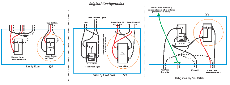
The orange circles are the switches I was working with. So I needed a Dimmer function at S1 or S2. S3 didn’t matter.
The easiest place to put a new dimmer is in the Living Room (S3)…easy. But how do I get the dimming function at S1 or S2?
Aha! I can use the Inovelli Association function and put another dimmer in place of S2. I can do this because fortunately I have Power and Neutral in the same box.
This is what I ended up with:
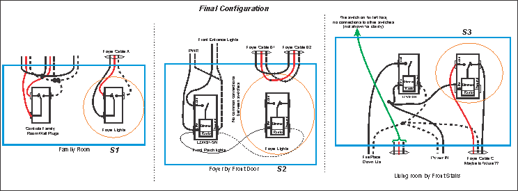
I jumpered the wires that were going to the 4-Way switch, essentially making it a 3-Way circuit. Then I added a Red dimmer powered by the circuit for the Front Porch Lights.
Association:
All we had to do was associate (using Inovelli’s association tool, at least in Hubitat) the ON/OFF and Dim Functions of the Foyer dimmer (S2) with the dimmer actually controlling the light (S3).
This simply tells the S3 dimmer to listen for S2 commands.
The effect is that S2 is mirrored in S3. So when I press the top of S2, the controlling dimmer (S3) hears this and treats it like you pressed the top of S3.
This is not a fancy new implementation but the same as shown in the Inovelli wiring guide. It simply shows a real life example.
BTW it took me some time to sort out all the initial wiring. What I do is draw the box and all the wires entering, exactly as you see them. This is why the two boxes on the left have wires on the top and the 3rd box has them on the bottom. If you looked at them they exactly as I drew them.