A ceiling fan and ceiling lights are on the same circuit as the kitchen 4 way switch you helped me with.
Now the fan and ceiling light will only turn on if the kitchen light is on. The fan and ceiling lights are on a 1 way switch.
A ceiling fan and ceiling lights are on the same circuit as the kitchen 4 way switch you helped me with.
Now the fan and ceiling light will only turn on if the kitchen light is on. The fan and ceiling lights are on a 1 way switch.
Since we took the black wire from the twisted black wires and attached it to the line input on the inovelli, I was wondering if we just connected a wire from the line on the inovelli to the twisted black wires would solve the problem.
Thanks,
Bruce
Do you have any pictures of the original wiring and dumb switch before you started? Or can you put everything back the way it was before you started installing the Inovelli? It’s very difficult to make much sense of the picture you posted since you have 4 blacks that are not connected to anything.
Forget the last post. I just realized how stupid that was. If anything, it would probably keep the lights on all the time. At the worst, it would blow the circuit. Hope you can help.
Questions:
Was the fan and light operated by the same switch before you started the inovelli installation?
Where is/was the 1 way for the fan (i.e. is it in the same box you posted a picture of?
pls identify the function of the middle and left switch.
I think the solution will be to pull out the switch on the far left of your photo and figure out what each Romex cable is connected to.
I’m Hoping:
a) power in
b) fan out
c) kitchen light circuit out
d) kitchen 4-way / 3 way connection
e) ???
In the pictured box is:
I’ll try to pull switches again later on. Wife just home from the hospital, and is a handful at the moment.
Wish your wife well  (most important thing).
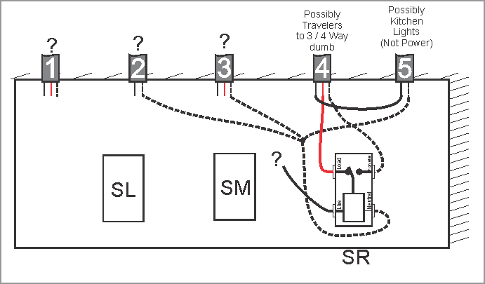
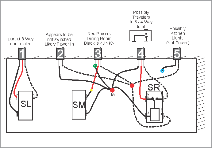
When you have time take a look at the below diagram. I’ve only been successful in these cases if we can figure out what wires are where. Its not as difficult as it looks.
This is what I think you have:
My wife is weak, but improving, thanks.
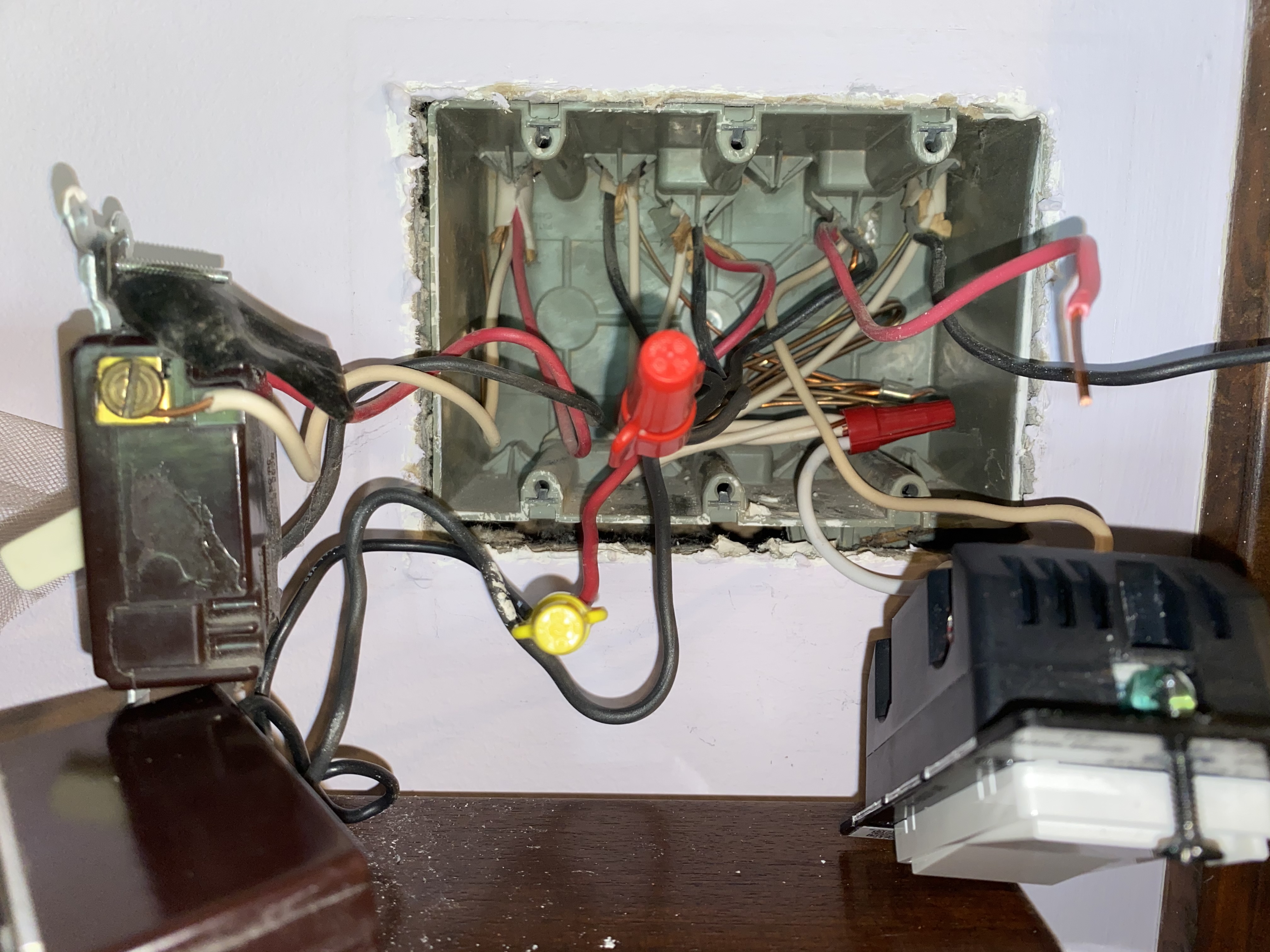
I’m uploading a picture of the box with switches pulled out. Left switch is 3 way for wall plugs in living room. Middle dimmer is for dinning light. Right switch is the 4 way we’re working with. Hope you can figure it out.
OK
We’ll ignore the left switch and cable “1” as they are isolated from the rest.
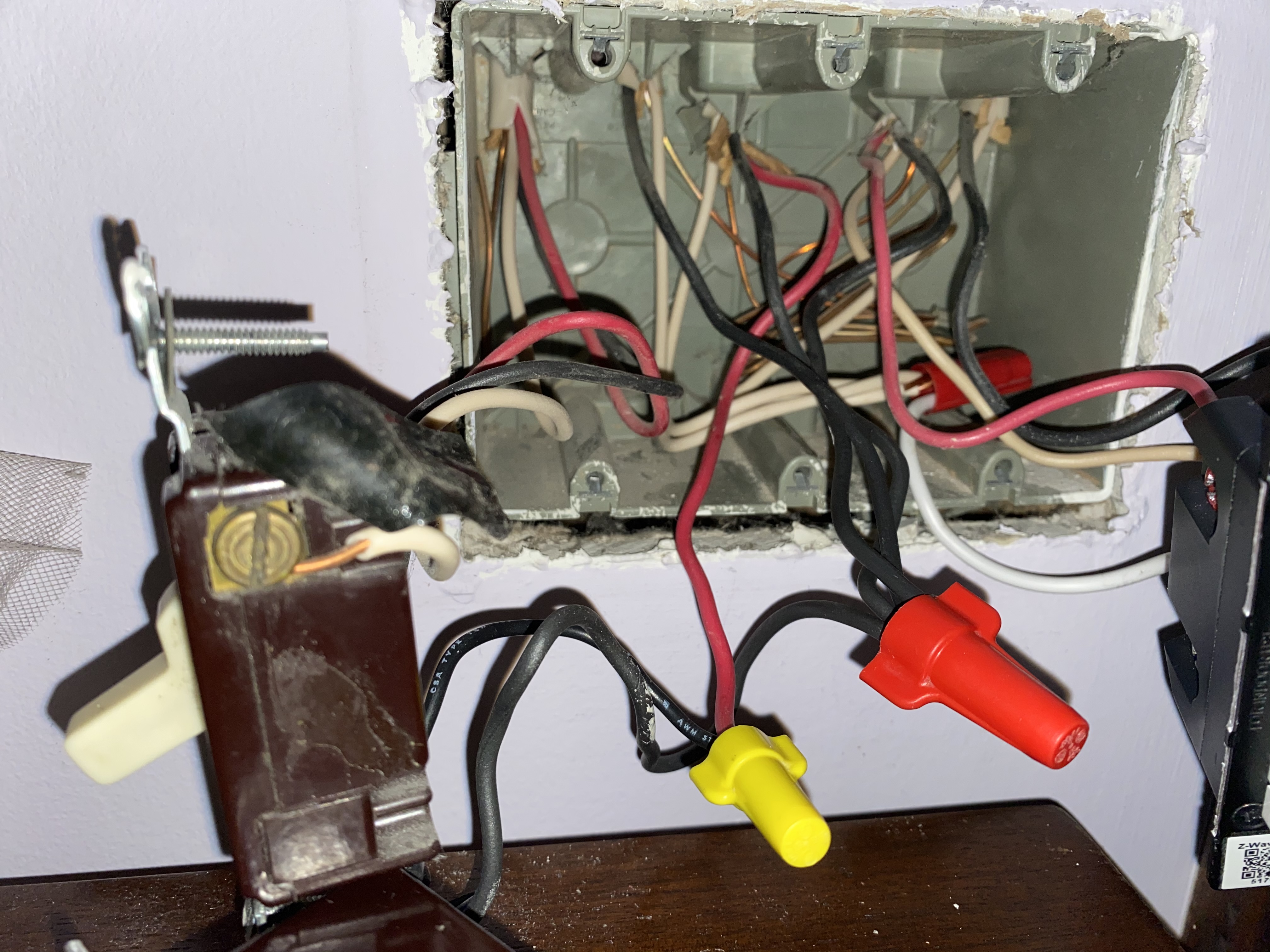
If it is still apart can you take another similar photo with the center Red wire nut pulled down so we can see the blacks?
So I’m sure, the functions are:
Middle is dining room light
Right is for the kitchen lights.
The issue was the fan would not go on unless the kitchen lights were ON is this correct?
Where is the control/switch for the fan?
I have an idea where we went wrong but still have to sort out the wires.
All the lights and fan on this circuit would not go on. The fan control in another box on the wall in the family room.
Is it me or is the BLK and RED in the middle bundle being fed by the LINE (2nd ROMEX bundle from the left). Seems weird it would be taking a line with both, but not knowing what’s on the other side, it may make sense? Also the two blk wires on the brown switch…why is there two hots going to this switch? The RED and YELLOW wire nuts are hot.
Picture was helpful.
Here is what you have now:
We still don’t know exactly how Cable C4 is wired and we are not sure of cable C5.
So lets see what C5 powers:
Disconnect the load and traveler from the dimmer. Leave them taped for now.
Connect C5black (blue ring) to power (i.e Junction Ja) It might be easier to connect it to the 2nd hole in the dimmer line input.
Something should go on:
I understand its a slow process but that’s what it takes. Or else we’re guessing. So if we just plod on we’ll get there.
John
Not trying to jump in on @JohnRob’s process, just letting you know what I see here. John’s diagram is accurate. I see remnants of the old dumb switch wiring.
That bundle of blacks is likely the constant hot for the box. The black from the 3-wire is connected to that bundle because that’s how you do it with dumb switches. The hot gets passed to the other end where it gets switched coming back the other way. It makes it’s way to the common terminal on the first switch then up to the light.
So from my perspective, you pigtail a hot to the switch and then tie the two blacks from the 2 and 3-wire together.
But @JohnRob is correct that you need to take this one step at a time to test.
Sorry to intrude . .just jumping in with my thoughts.
Back to @JohnRob
Thanks Bry, that solution worked.
John, I want to thank you for all your patience and help. You spent a lot of time with me, and I really appreciated it.