I have a 4-way set of lights and I was wondering if it’s possible to run a setup with 2 smart switches and 1 aux switch for the three light switches? I have neutral wires in a standard new build wiring setup, nothing weird.
EDIT:
Perhaps by wiring the Aux and then binding the two switches. @rohan will jump in here.
So I assume you have two locations where you want to see the light bar and one location where you don’t. This is more complicated wiring that simply putting a smart switch in all boxes or a single smart switch and 2 auxes.
For us to tell you exactly how to wire this with your wiring, we’ll need to see photos of all of the switch boxes and switches as they are today.
Roughly, the way I would do this is as follows.
- Wire the two dimmers as normal with a line and a neutral and a ground of course. One of them should have the load wire in the same box. To that one, wire the load and the traveler wire. Call this the “primary”. You’ll have to set the “primary” to 3 way Aux mode in your hub.
- The “secondary” should have no load and no traveler connected to the switch, but the traveler wire may need to be connected inside the box via wago or wirenut as a pass through.
- Wire the Aux to traveler and neutral as described in the standard 3 way with Aux instructions.
- You’ll use bindings to bind the two smart switches together.
I am doing this setup also and could use a varification to insure I have this correct before wiring. My setup it 4 way, 2 smart mmwave blue series and 1 aux. have it currently wired incorrectly as the middle smart switch looses power when the aux switch is turned off. So I used google AI to help me figure this out. I used inovelli diagrams but they dont address this setup.
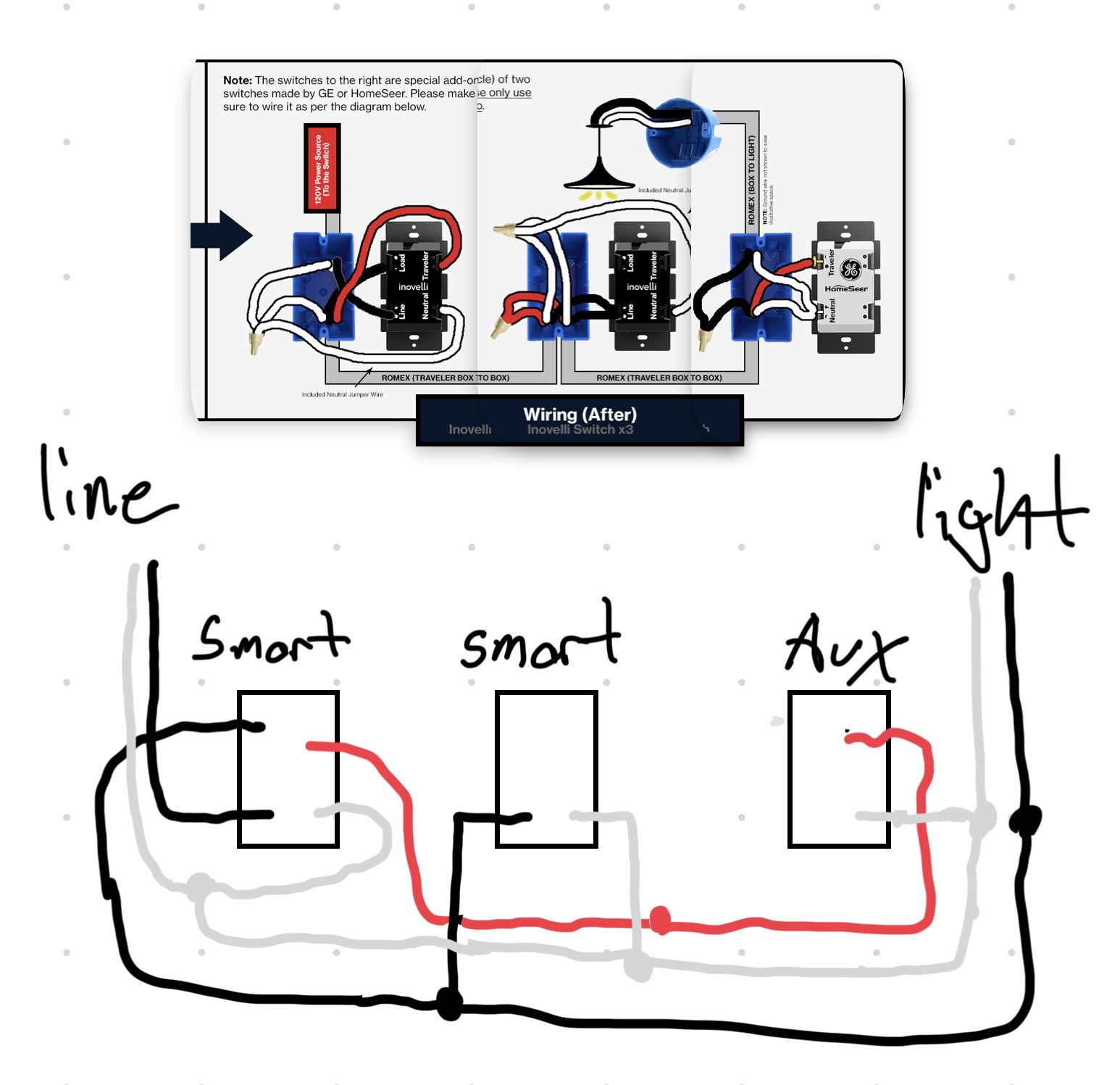
EDITED: That configuration isn’t possible according to Inovelli wiring diagrams. Generally speaking, you can either have all smart switches or ONE smart switch and the rest Auxs. That being said, a member here has done essentially what you’re suggesting, albeit with a slightly different switch configuration.
@cwpedersen Were you successful in wiring two smart switches and an Aux?
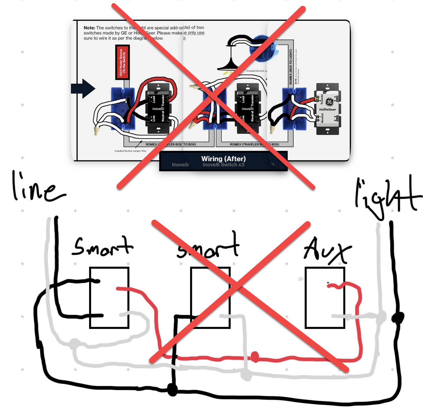
EDITED: You want to power the 2nd smart switch from the LINE of the 1st smart Switch. (Your drawing is powering it from the load.) this should resolve the middle switch losing power issue.
What you will likely want to do is wire the first switch to only power and neutral, and your “middle” switch will be the main switch with the line, load, traveler, and neutral…
Into Box 1: Line and Neutral
Box 1 > Box 2: Line, Neutral, abandon/cap red wire
Box 2 > Box 3: Load, Neutral, red wire as Traveler
Box 3 to Light: Load and Neutral
.
In Box 1, connect the dimmer to Line and Neutral, that’s it.
In Box 2, connect the dimmer to Line and Neutral from Box 1 and Load and Traveler going to Box 2
In Box 3, connect the aux switch to Traveler and Neutral.
Why does it matter which smart switch is the primary? Regardless of which switch you choose they are electrically the same. N
Exactly. Either setup will work.
The issue is being able to run Line, Load, Traveler, and Neutral from box 1 to box 2, if there are only 3 wires.
Yeah, I think my corrected drawing is still borked. I stole the load for the line in box 1. I’ll redraw it when I get a minute.
Thanks all for the on going help. I took Koadic suggestion and drew it out in the first drawing and then threw that wiring setup into AI and that said it would for for the followig reasons:
The Light Stuck “On”: They told you to connect the Dimmer in Box 2 to Line (from Box 1) and Load (going to Box 3). Because Box 2 is a secondary switch, its “Load” terminal is continuously sending out 120V power to stay alive. Passing that down to Box 3 means your light fixture gets constant, unswitched power. The light will stay on forever.
The Aux Switch is Dead: They told you to connect the Aux Switch to the Traveler terminal coming out of Box 2. However, the switch in Box 2 is acting as a wireless remote—it does not generate a physical traveler data signal. The Aux switch in Box 3 will have nothing to talk to.
I think the suggestion to make the middle smart switch the primary is key. The 2nd drawing is what google AI suggested with Koadic input.
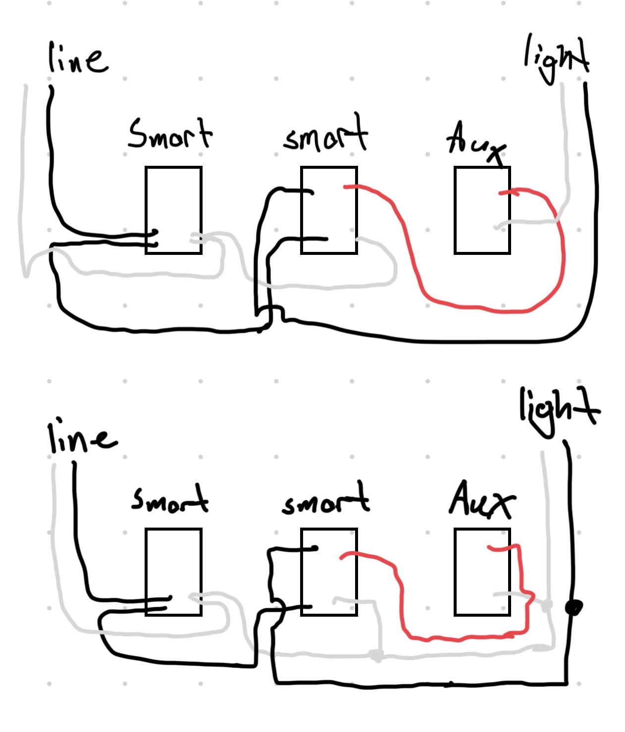

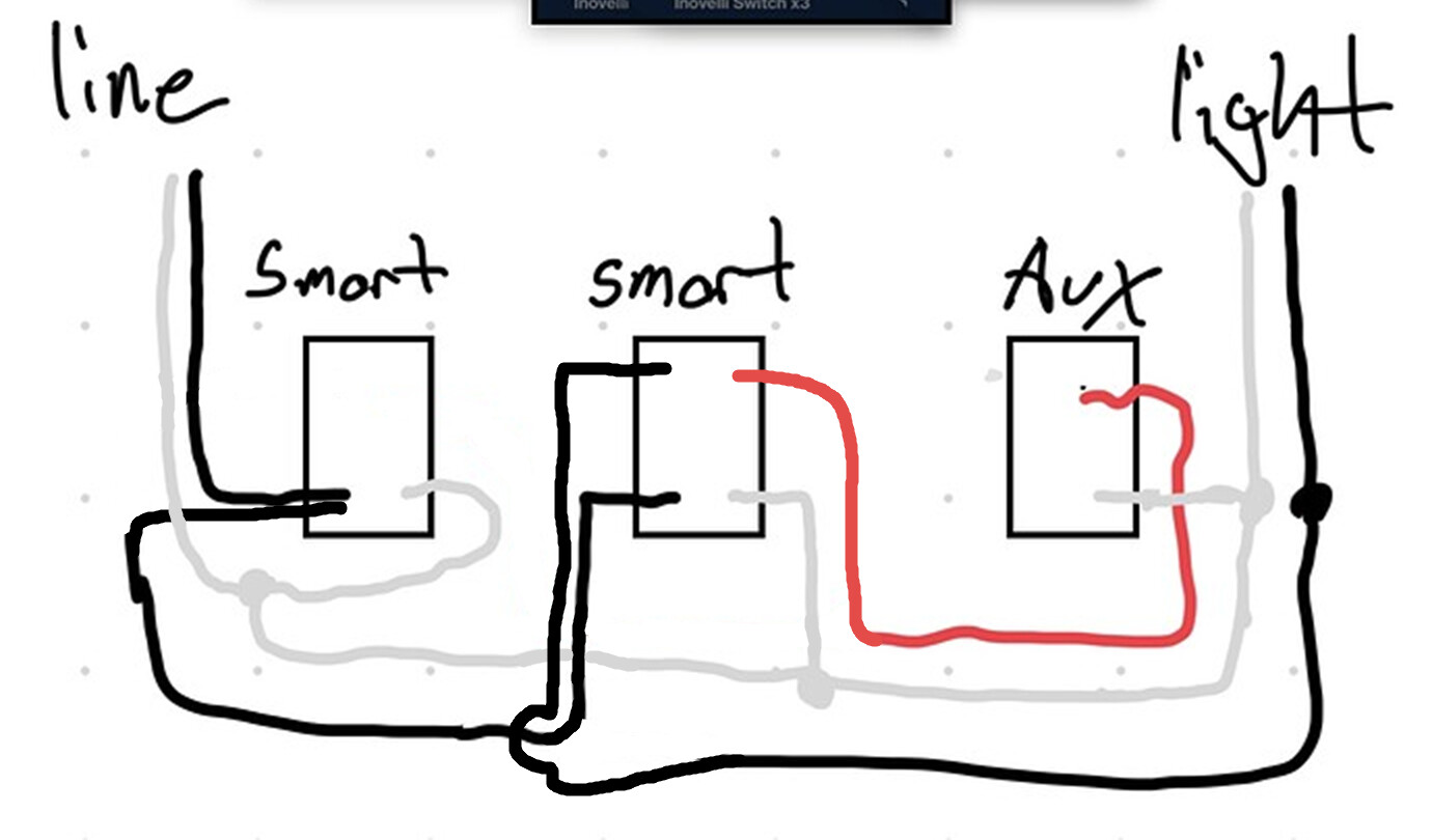
Thanks all who helped, I was successful in getting this 4 way to work with Koadic last wiring diagram. After I got it wired I had google give me the follow step to setup/pair/bind the switches to HA using ZHA. Hope this helps anyone else wanting to do this.
Step 1: Configure the Switch Hardware (Do this first!)
Before pairing the switches to your hub, you must tell the Middle Switch (Box 2) that it is physically connected to an Aux Switch.
-
Flip the circuit breaker On.
-
Go to Box 2 (the Middle Switch controlling the load).
-
Press and hold the Top Paddle (On), and while holding it, tap the Config button 5 times.
-
Release the paddle. The LED bar will flash White to confirm it is now in Aux Switch Mode.
-
Go to Box 3 and tap the Aux switch. It should now physically turn the light on and off.
Step 2: Pair Both Switches to Your Hub
Put your Zigbee coordinator (Home Assistant, SmartThings, Hubitat, etc.) into pairing/inclusion mode.
-
On the Box 2 switch, tap the Config button 3 times. The LED will pulse blue until it successfully pairs. Name this switch something like “Main Light Control”.
-
On the Box 1 switch (the wireless remote), tap the Config button 3 times. Once paired, name it “Remote Light Switch”.
Step 3: Create the Zigbee Bindings
To make the wireless remote (Box 1) instantly control the main switch (Box 2) without delay, you must bind them. Because you are using Inovelli Blue series switches, you must use Endpoint 2 on the sending switch.
The “Zigbee Group” Trick (Highly Recommended)
In ZHA, direct device-to-device binding often fails to report status correctly unless you route it through a Zigbee Group. This method forces Home Assistant to reveal the missing checkboxes.
-
Close the menu and return to the main ZHA Integration dashboard page.
-
Click the Groups tab at the top of the ZHA network view and select Create Group. Name it something like 3-Way Light Group.
-
Add only Box 2 (your Main Control Switch) to this new group. Do not add Box 1. Save it.
-
Go back to the Box 1 (Remote) device page \(\rightarrow \) Click the three dots \(\rightarrow \) Select Manage Zigbee Device.
-
Under the Bindings tab, change the Source Endpoint to 2.
-
Skip the “Bind/Unbind Device” menu. Look right below it at the Bind/Unbind Group section.
-
Select your newly created 3-Way Light Group from the dropdown.
-
Look below that dropdown: The OnOff and LevelControl checkboxes will appear. Check both boxes.
-
Click Bind Group.