Hi,
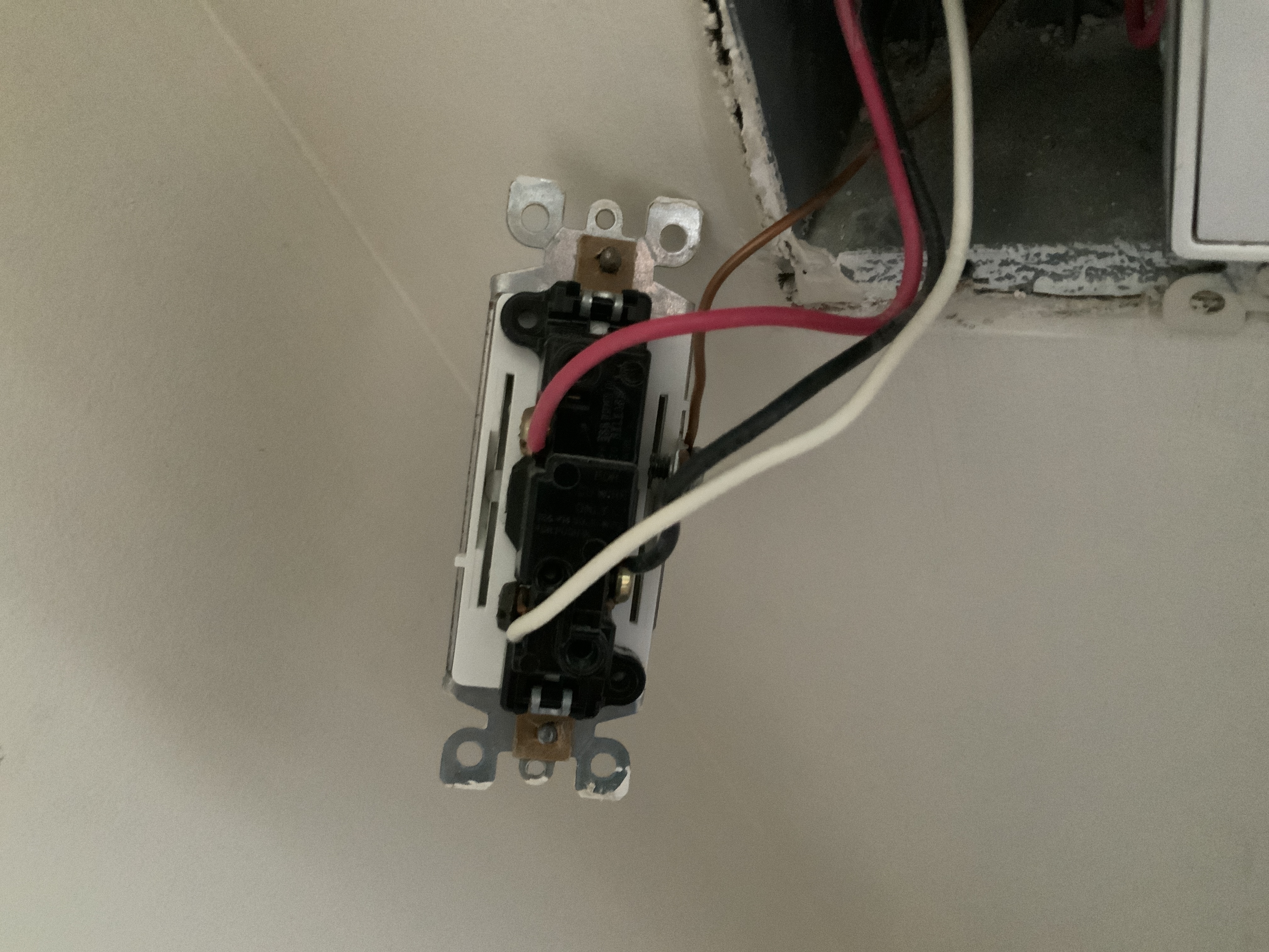
I’m trying to install my new Red Series dimmer in a 5-way installation. I was looking at the diagrams in the manual, but my installation seems to be different. The issue is that on the current switch, neutral and common are across from each other. Then the traveler is on top. Does anyone know how I should connect the Inovelli? I have a multimeter that I could test with if needed. Thanks so much! I greatly appreciate it.
Is this the switch into which power is fed? How did you determine that?
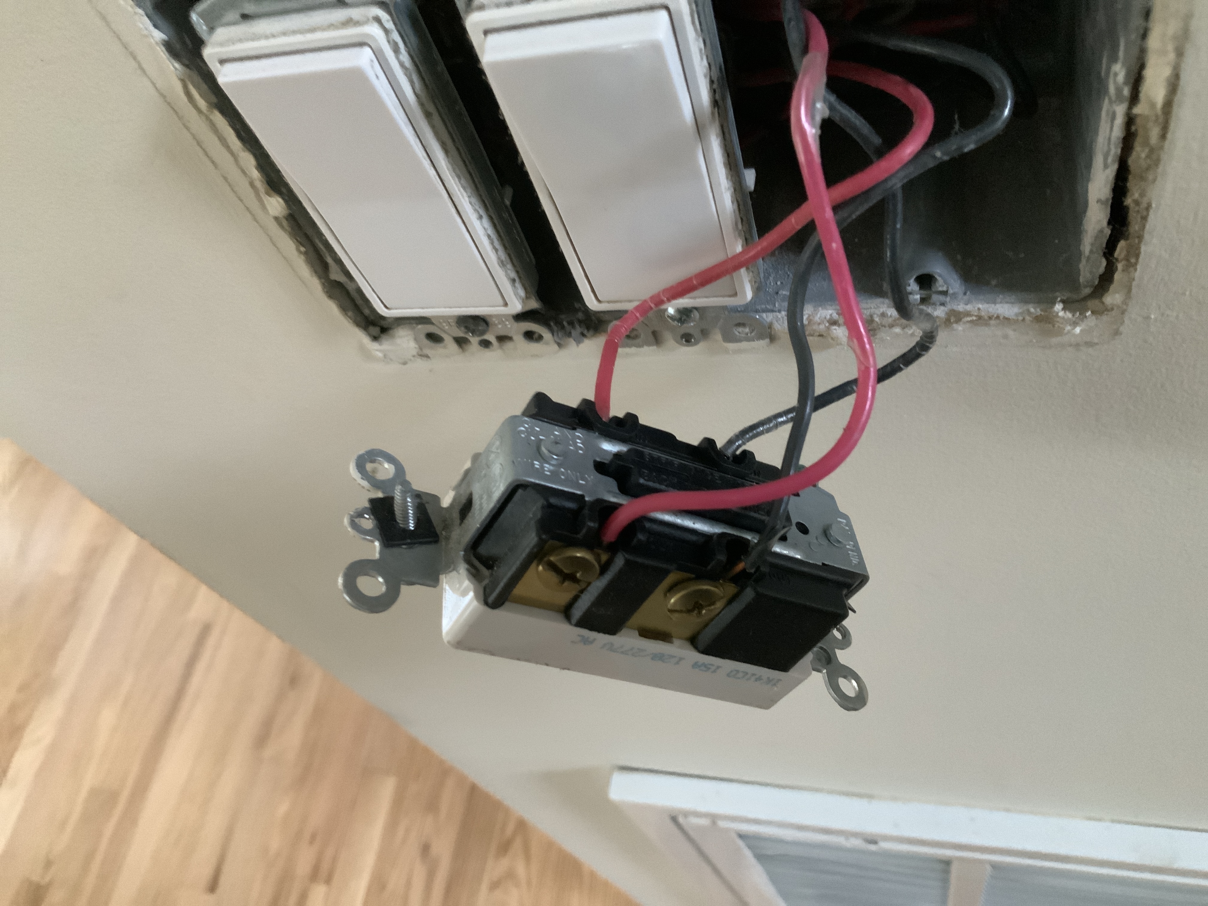
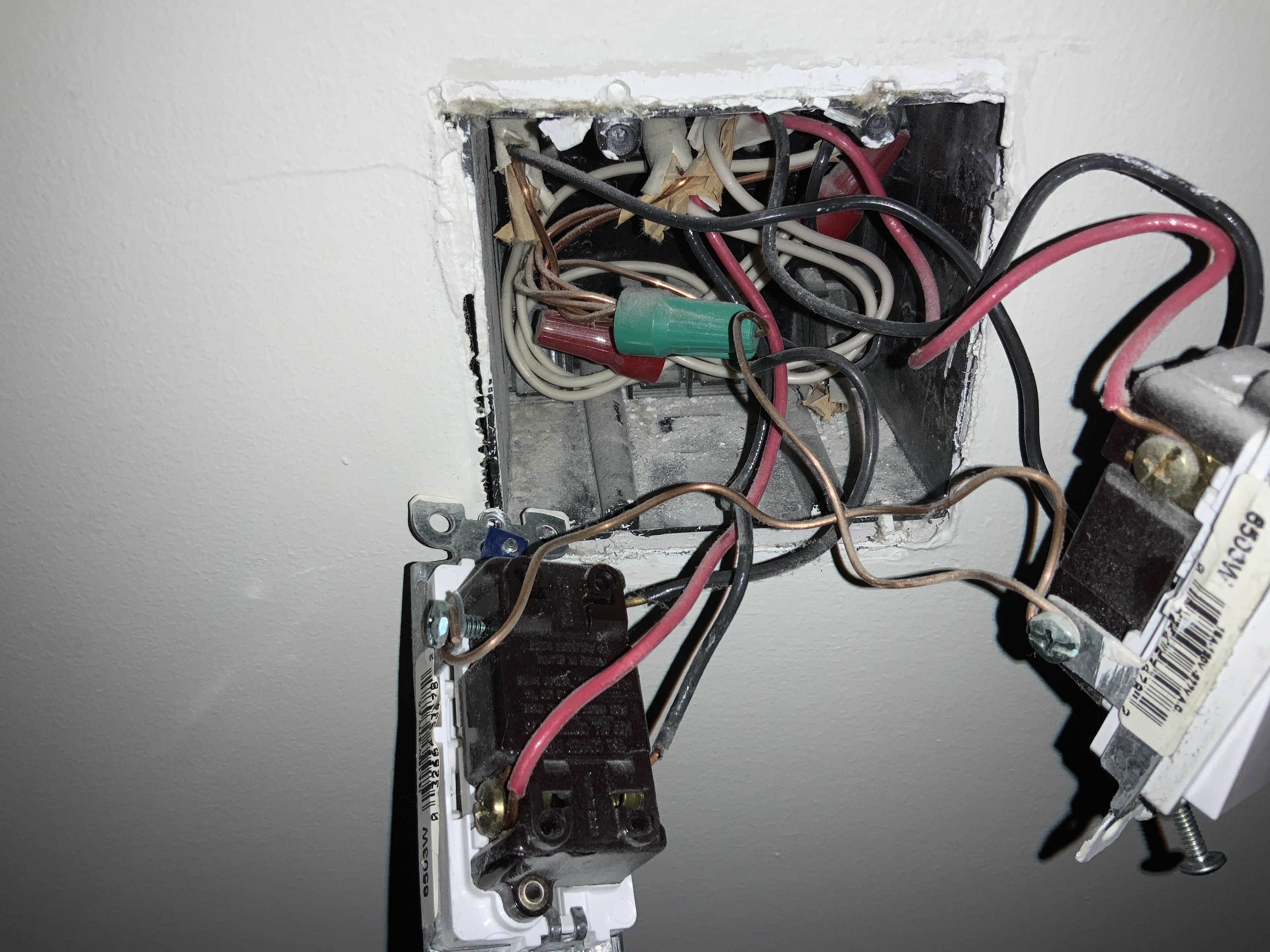
We need a pic to see into the box with the 3-way switch to see how many Romex are involved. Can’t tell much without it.
All but one other, actually. The last switch will be a 3-way, not a 4-way. Do you know where that one is located as you may need to look at that one as well?
Thanks so much for responding. I (maybe falsely) assumed that that the first image was the main switch because it had a neutral wire and the others didn’t. That switch has one romex going to it. The other in the box goes to a separate outdoor circuit. Also, you’re correct that the last switch is different. This one has many romex in the box, so maybe its the first one…).
Inside the box (the other romex is for the outdoor circuit… they’re not connected at all):
I actually got excited and spoke too soon . While it is working and all of the switches work, toggling any dumb switch cuts power to the dimmer completely, meaning it can’t be turned back on from the dimmer. I configured the parameters but it didn’t help. I think I’m going to attempt to trace the wires and label them properly.
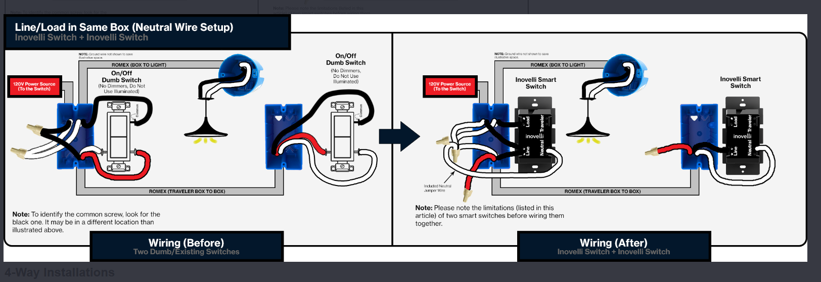
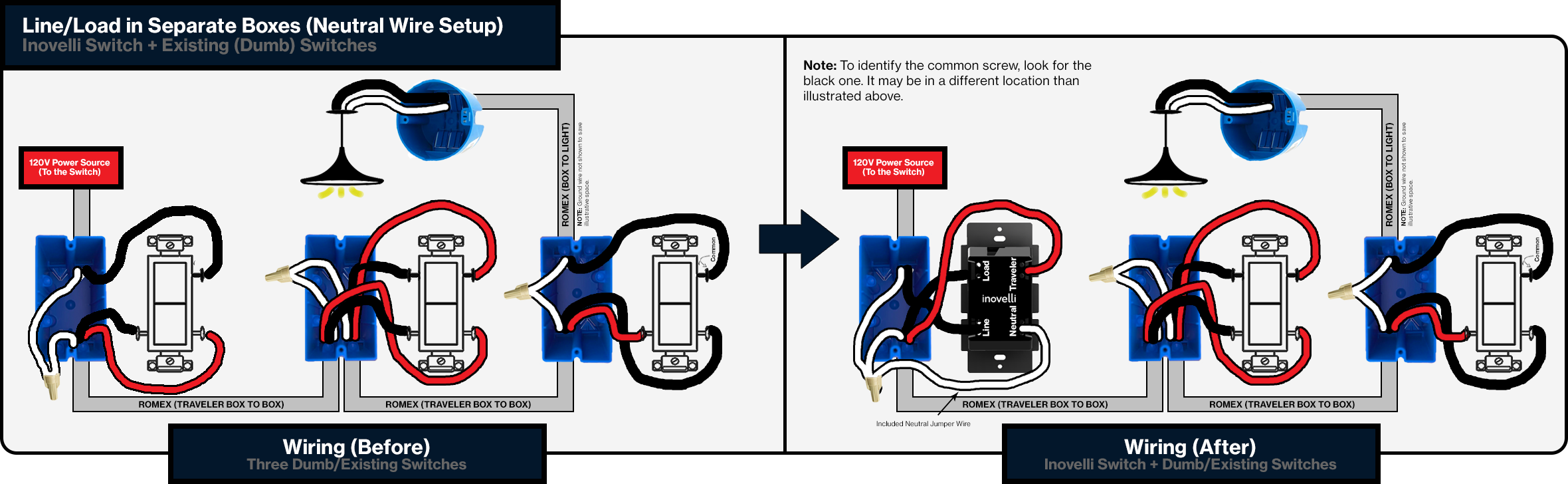
In a 4+ way switch configuration, you will have 3-way (i.e. 3 terminals) switches on both ends with 4-way (i.e. 4 terminals) switches in the middle. Power (the Line) starts at one end at one of the 3-way switches. The light (Load) can either be in that same box or be at the other end.
You posted pics of one of the 3-ways. According to you and verified by the pics, that terminals on that 3-way switch are all connected to that one Romex. That suggests to me that you have a Line and Load in the same box configuration.
So based on the limited information you’ve provided, I think that your Line and Load are in the OTHER 3-way switch box. That’s where you will put the Inovelli. If I am correct, you will see three Romex involved. You’ll have one 2-wire that is a hot and neutral, one 2-wire going to the light (load) and one 3-wire going to the other switch.
Got it working with the schematic (for dumb switches) and by finding the 120v power source wires with my multimeter. I’m happy with the switch and I’ll be replacing all of my dumb and GE switches with Inovelli when it comes time to remodel the house. Thanks so much!!

 . While it is working and all of the switches work, toggling any dumb switch cuts power to the dimmer completely, meaning it can’t be turned back on from the dimmer. I configured the parameters but it didn’t help. I think I’m going to attempt to trace the wires and label them properly.