I have been having a great time installing Inovelli Blue series dimmer switches (VZM31-SN), until I hit this weird circuit I just can’t seem to reason through.
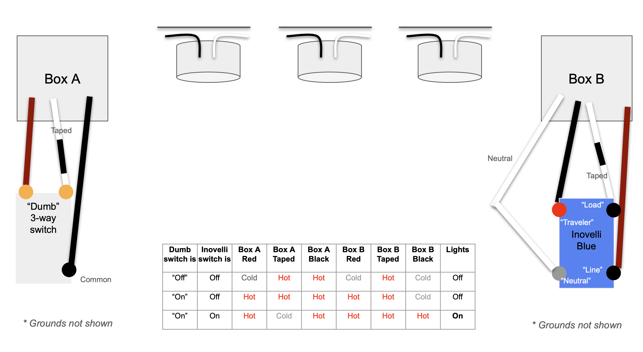
This is a 3 way circuit with two dumb switches, three overhead cans, and two boxes. One box (box B in the diagram) has a neutral wire available. In both boxes, there is a red wire, a black wire, and white wire that has been taped over (re-identified?). I want to install our Inovelli switch in one box (ideally in B since it has the neutral wire) and keep the dumb switch in the other.
Google suggests this might be a “switch loop”. Unfortunately I don’t have access to the light fixtures so I am doing some guesswork re: how everything is wired together.
I currently have everything wired like this (see diagram) and have used a tester to see which wires are ‘hot’ in each switch position. Today, when the dumb switch is “on”, the Inovelli functions as expected, lights turn on and off. When the dumb switch is “off”, the lights are off and Inovelli starts cycling Cyan-Blue-Yellow-“click”, indicating a wiring issue.
This is how I currently have the switches wired, though I have tried pretty much every configuration at this point…
Are these both in single gang boxes or is at least one of them in a box with other switches? I am asking because you said one box has a neutral wire available but I do not see that in your drawing. While the white conductor is typically used for the neutral, it may not necessarily be a neutral in some wiring configurations.
Based on your wiring colors, I am guessing that you have Romex or some other sheath cable where all three conductors are run within an outer jacket?
In each box, are all three conductors from the same jacketed cable connected to the switch?
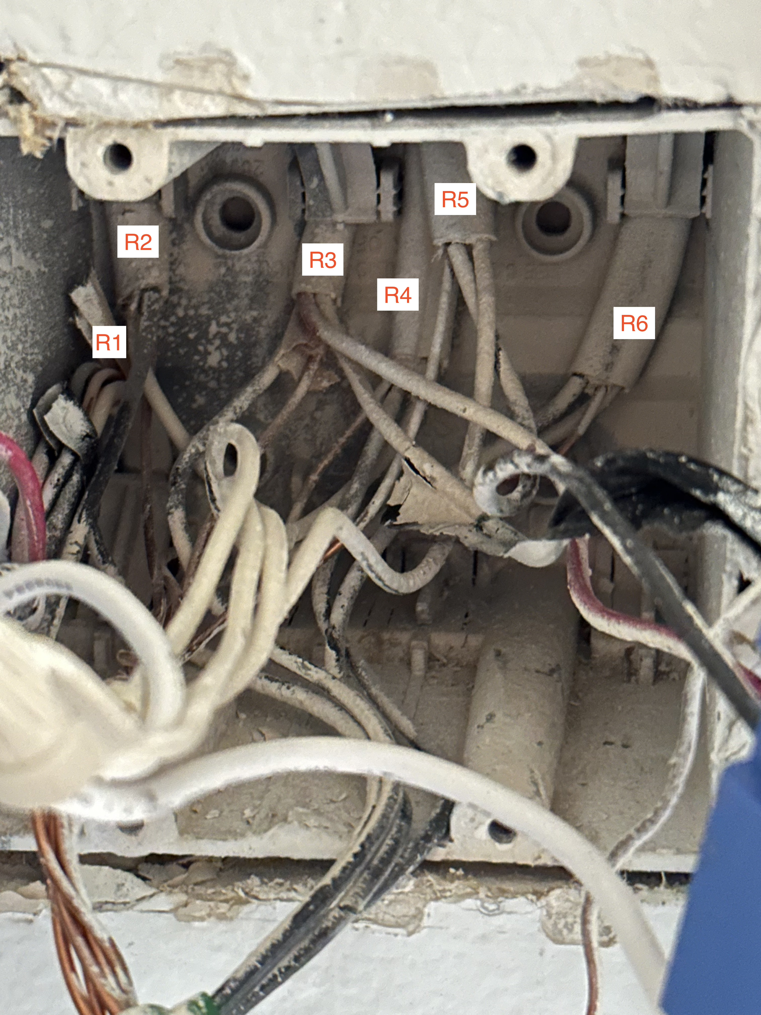
Thanks so much for your response. Box “B” is actually a double box with another 3 way switch with the same wiring pattern/issue. There are actually 6 Romex lines entering that box, it’s pretty hard to see, paint isn’t helping either:
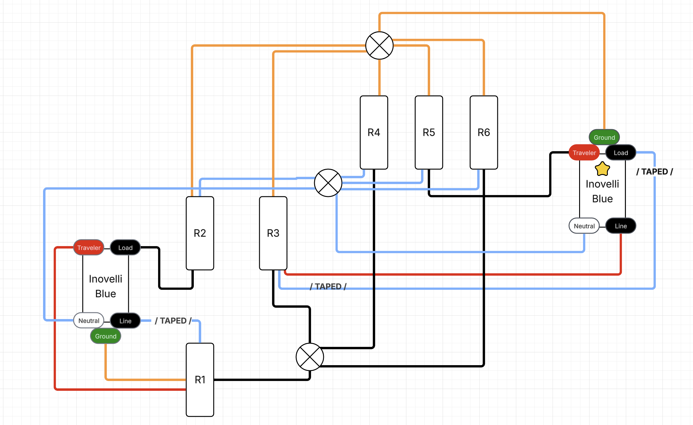
The circle symbols are electrical caps. Light blue represents white wires. The switch with a gold star is the one I am focusing on first.
I realize this is pretty gross and complex. I’m hoping this is a common pattern and someone will recognize it. At least they are all on the same breaker circuit.
Let’s start with the answer to my question. I’m going to guess “no” based on your 2nd drawing.
Thanks for the diagram, but a diagram of how inovelli switches are wired that are not working doesn’t help too much.
You are going to have to put the dumb switches back in working order so we can evaluate what you have going on. Then take pictures of the boxes so that we can see all the connections to the switch and into the box. If you can’t look at your picture and trace an individual conductor, we can’t either.