Hi. I recently installed about 10 Red Series dimmers and then had an electrician install a dimmer in a three way(kept dumb switch for now) and a four way(kept both dumb switches for now). Post electrician leaving, I realized I needed to change parameters and the like and still are having issues with the dumb switches shutting off the Inovelli. Since I don’t attest to being an electrician, I’m first curious about the three way setup in which I’ve attached pictures. I still have some more Inovelli switches so I’d like to replace the dumb switch with those to have scene control versus something like a GE Aux switch and then associate the two switches.I am a Hubitat user. I’m not entirely sure if my first installed Inovelli switch has power flowing thru it first. It is definitely the one I’d like the dimmer function as the other switch is out of the way and only comes into play when someone shuts it off. Thoughts on using the Inovelli or GE for those that have done it and can anyone tell me based on my pics if this is right? Moving on to the 4 way, I’d like to have another dimmer and an on/off. I only installed one dimmer at the Line junction box and my dumb switches turn everything off. A second dimmer would be in a location used by the family way more. Thoughts/advice again on going all Inovelli versus GE and associating the switches?
Thanks!
For a 3-way with a dumb switch, it’s going to have to be. If you have them reversed, they things will not work properly. If that is the one in the pictures, you can’t tell with what you have posted. Need to see inside of the box to see the other connections. Additionally you need to identify the source of your power (Line) and the wiring to the light (Load).
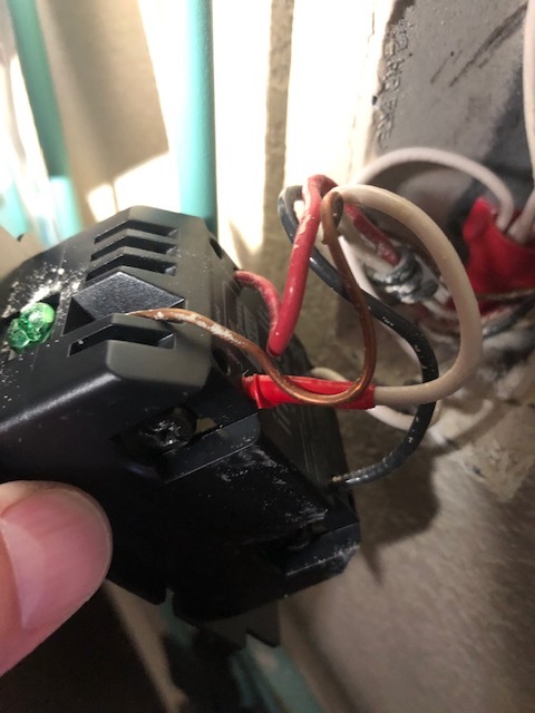
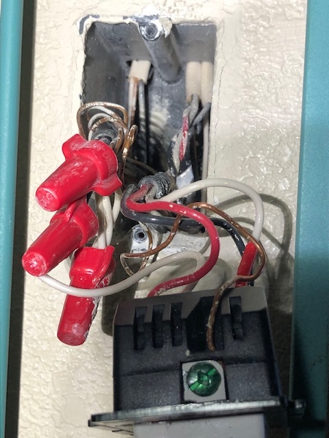
Here’s hopefully a better picture of the Inovelli switch. The white with the red tape would appear to be hot. I’m told that the 2nd dumb switch is a dead three way/no neutral from somebody looking at these pics if that helps.
So on the Inovelli side, it looks to me like all three wires attached to the switch are coming from the same 3-wire. Trace those wires to where they come into the box to confirm.
EDIT: That bundle of neutrals makes me pause. Post a picture of the Inovelli box with all of the bundles pulled out please.
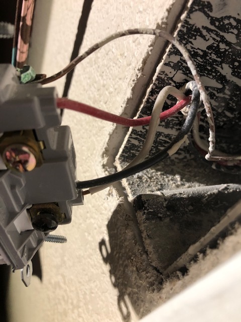
Then go to box with the dumb switch. I can’t see inside the box, but I’m guess all three wires come from the same 3-wire. No other conductors in the box. Please confirm.
I’ll open it up and take a picture tomorrow. Thank you!

So hopefully this is clear. Probably more pics than needed. So confirmed all the non neutrals are all coming from the same place including. And yes the dumb switch has all the wires coming from the same place.
Sorry, but I don’t understand that. But now I see another Romex that wasn’t visible before, so disregard that question for now.
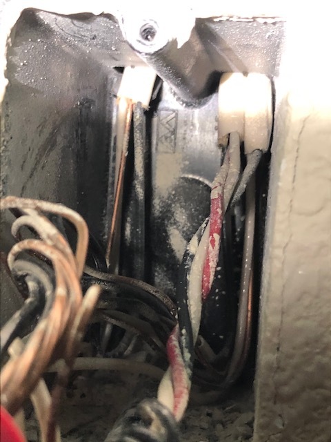
Thanks, but the Inovelli box doesn’t have all of the bundles pulled out. You have to reach in there and physically extend EVERYTHING so it’s clear where everything is connected. You’re doing this with the breaker(s) off, so after testing you should be able reach in there and pull everything out.
You have to understand that it’s important to see all conductors and their connections. If you don’t pull everything out, then it’s very possible some things may be hidden. I know from experience that it happens.
Take a look at your pictures and focus on that Romex coming into the box at the top right? Is it a 2-wire or a 3-wire? What is it connected to? Where is the black from the 2nd from the left 3-wire connected? Is i the switch or is that black in the picture really coming from the Romex in the corner? See what I’m trying to determine? (Don’t answer these questions . . just trying to give you a sense of what it takes to analyze a switch leg just by using pictures.)
Thanks.
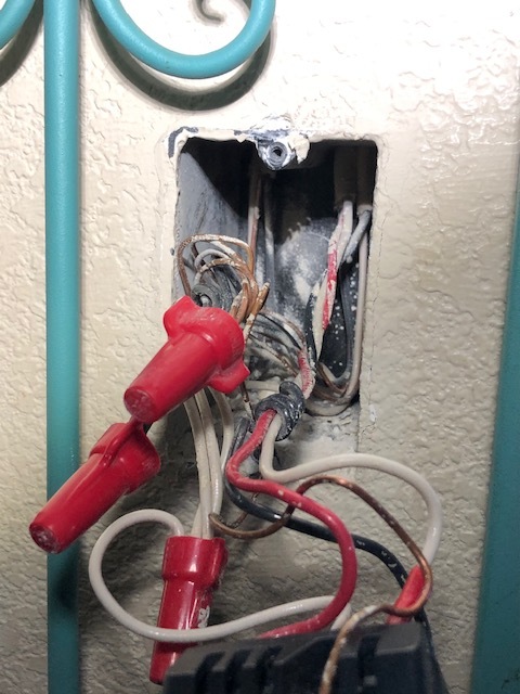
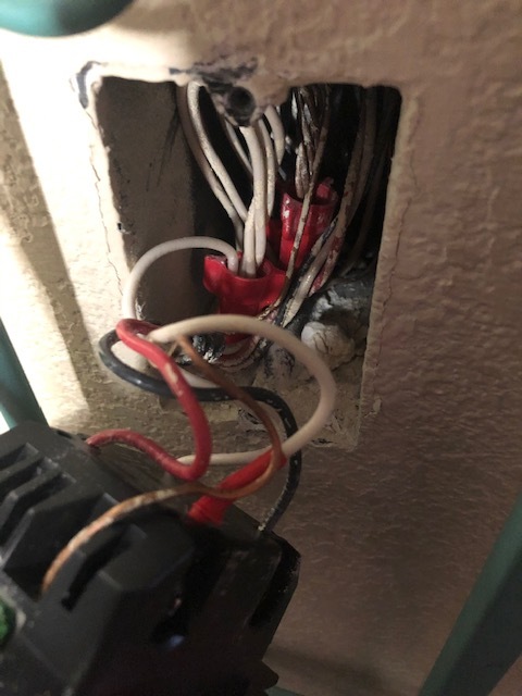
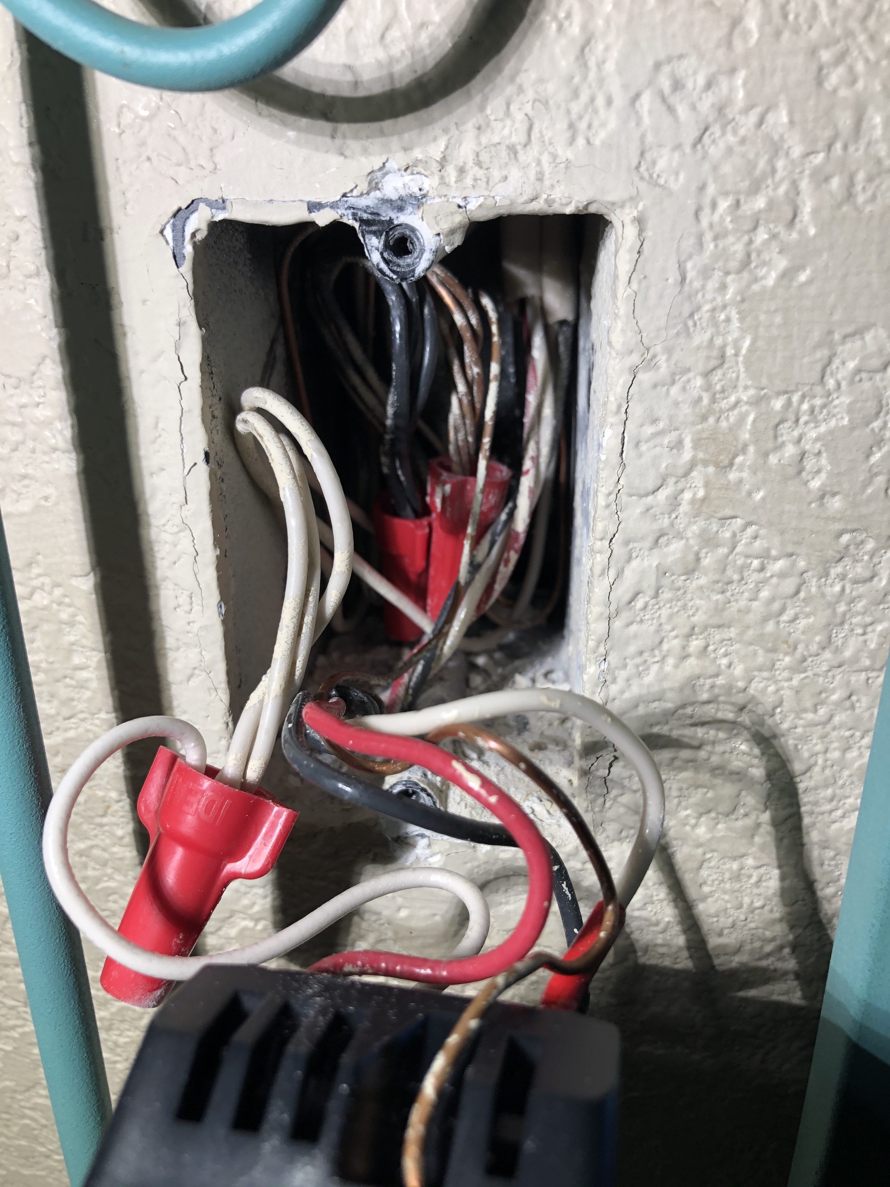
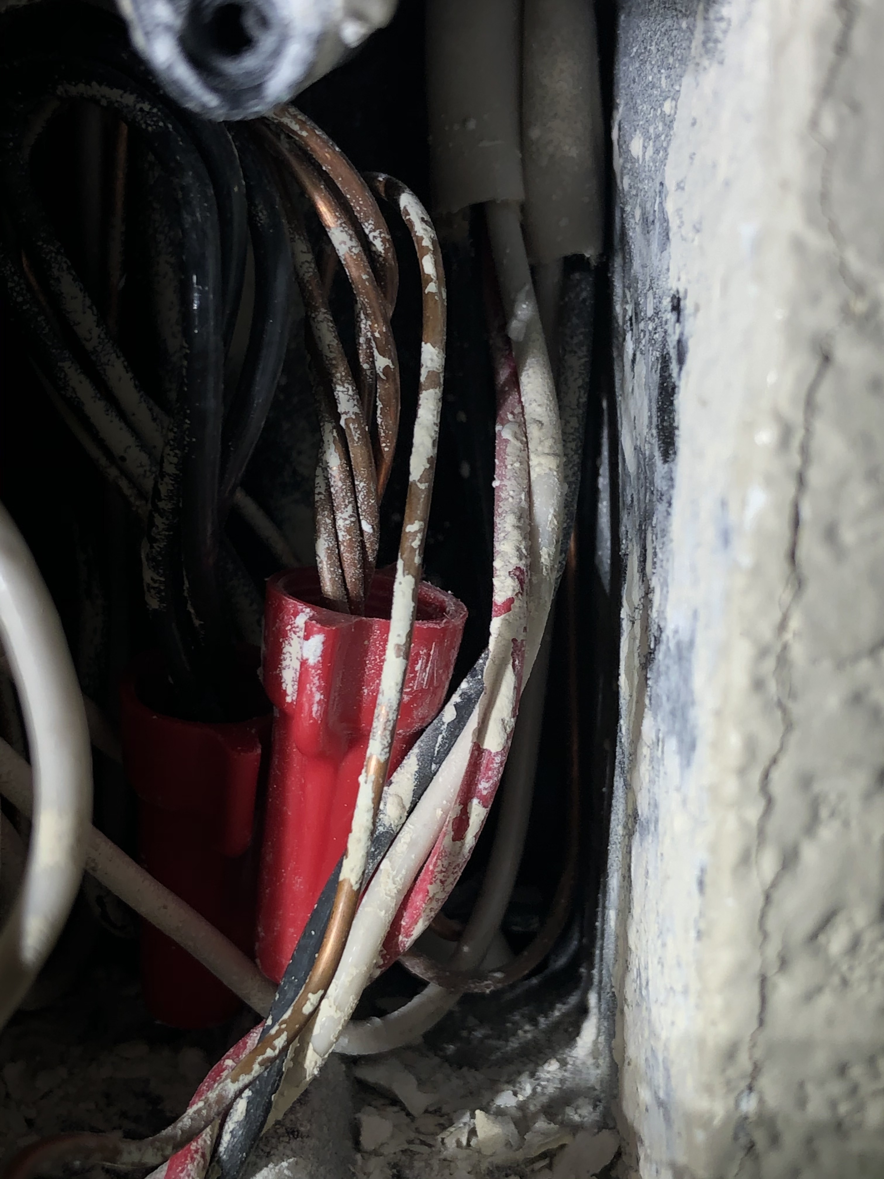
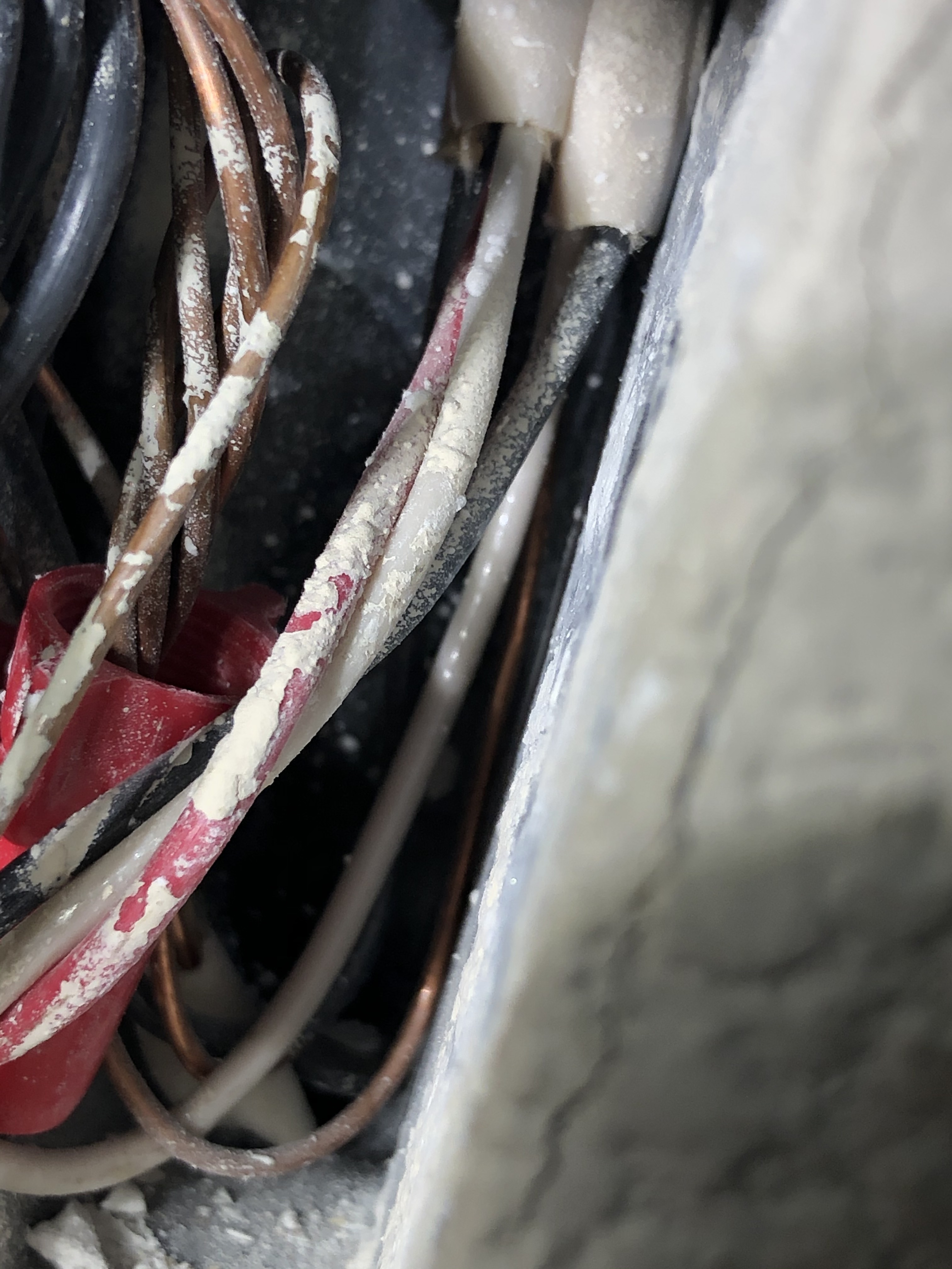
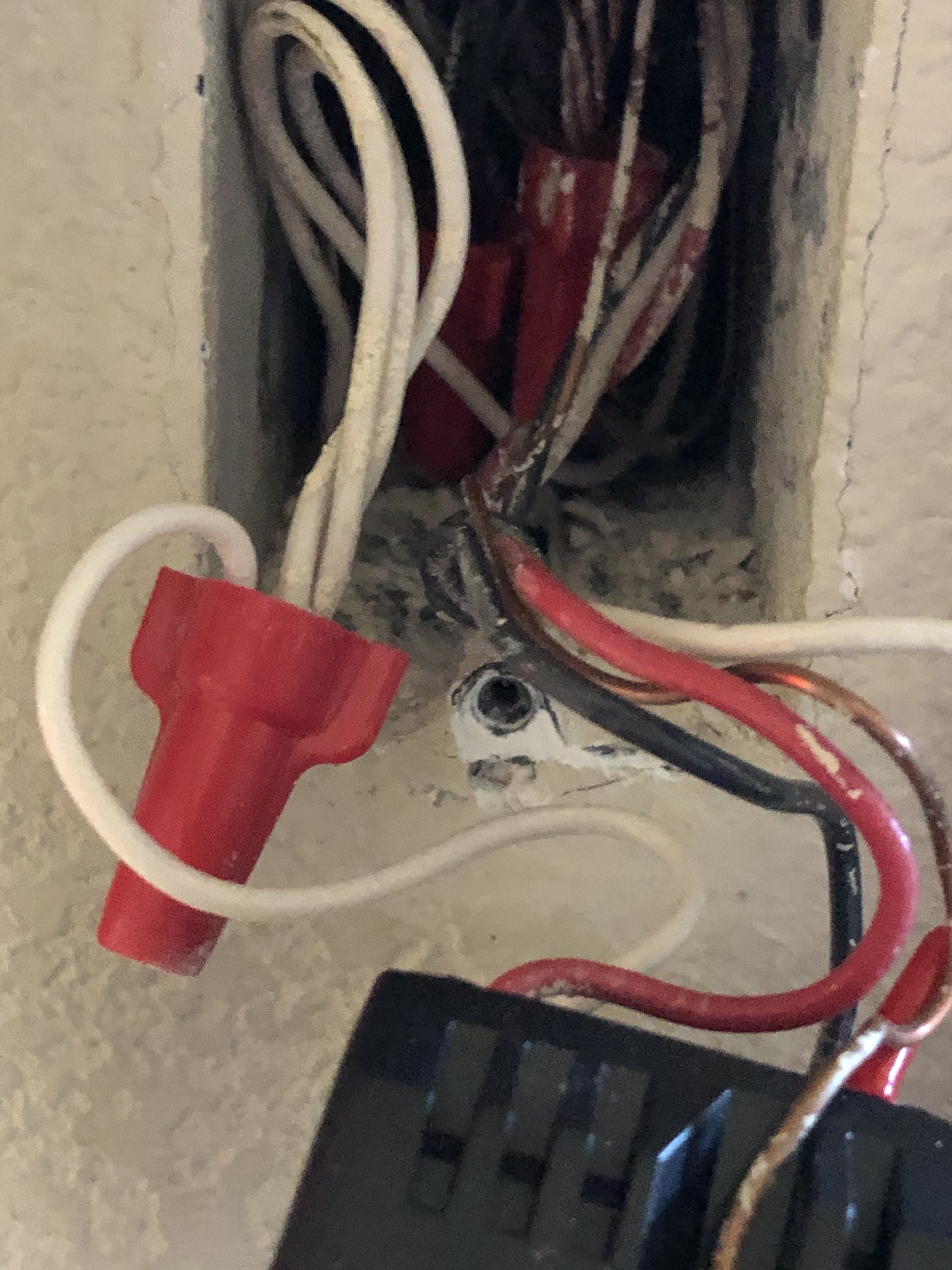
OK pulled them all out and realized wire photography is hard ;).
Essentially upper back right has 4 wires. The black wire goes into the wire nut with other blacks. The copper ground goes into the wire nut with other coppers. Same with the white ground. The last black wire then is wrapped around the wires from the next set of wires(and ultimately attached to line on the Inovelli) just to the left still in the back right. They are a red traveler leading to traveller in the Inovelli, a white (w/ red tape) attached to load on the Inovelli. A ground and neutral also attach to the Inovelli from those wire nuts. Upper left going out from the wire nuts are a white, copper, and black. Hard to see in the bottom of the box a white, black, and copper all come in to the appropriate wire nuts.
I hope this helps and isn’t more confusing. I applaud you for trying to help. Did I mention I’m not an electrician but willing to pretend to be one on the internet?
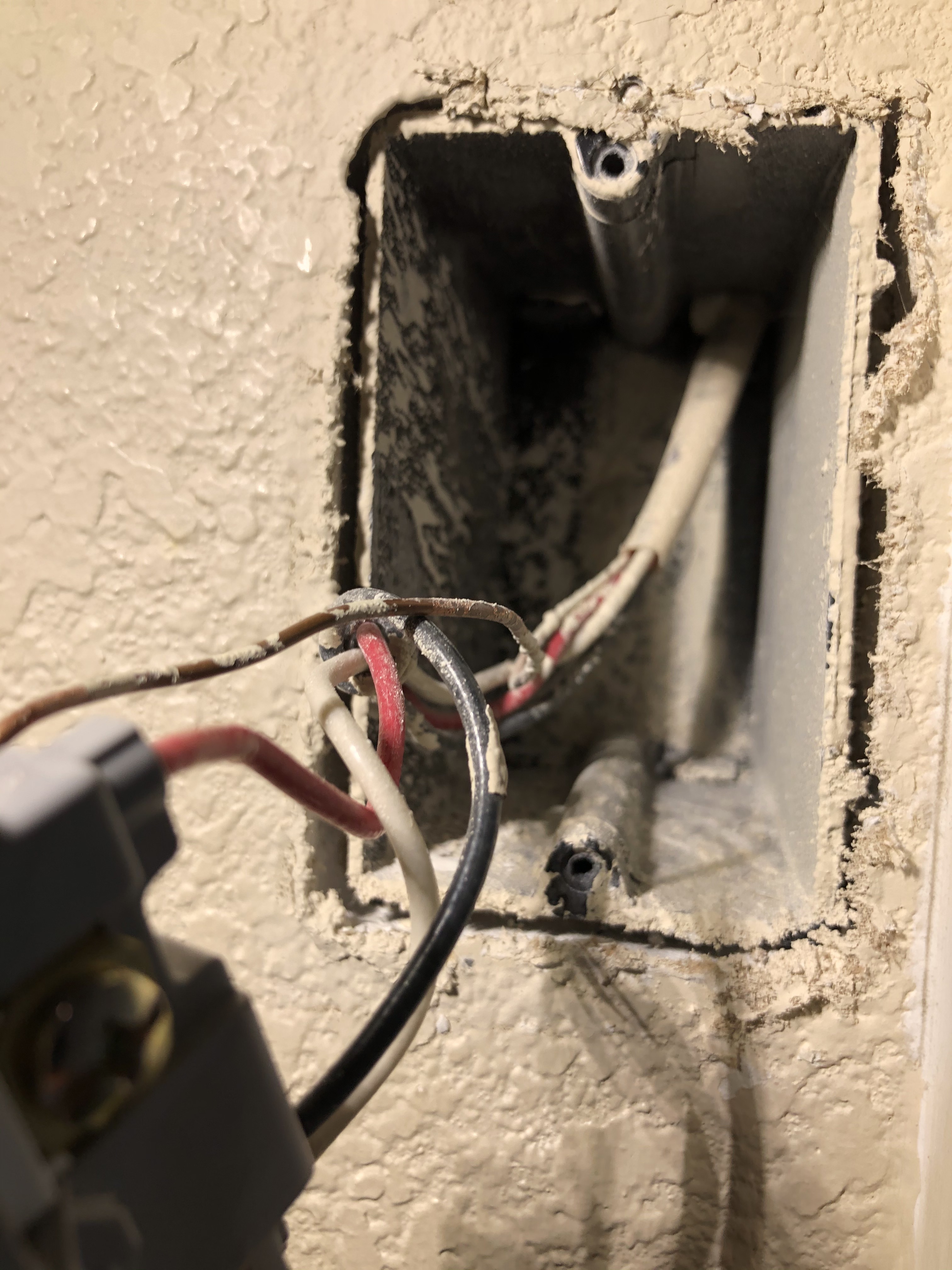
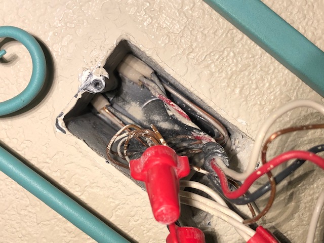
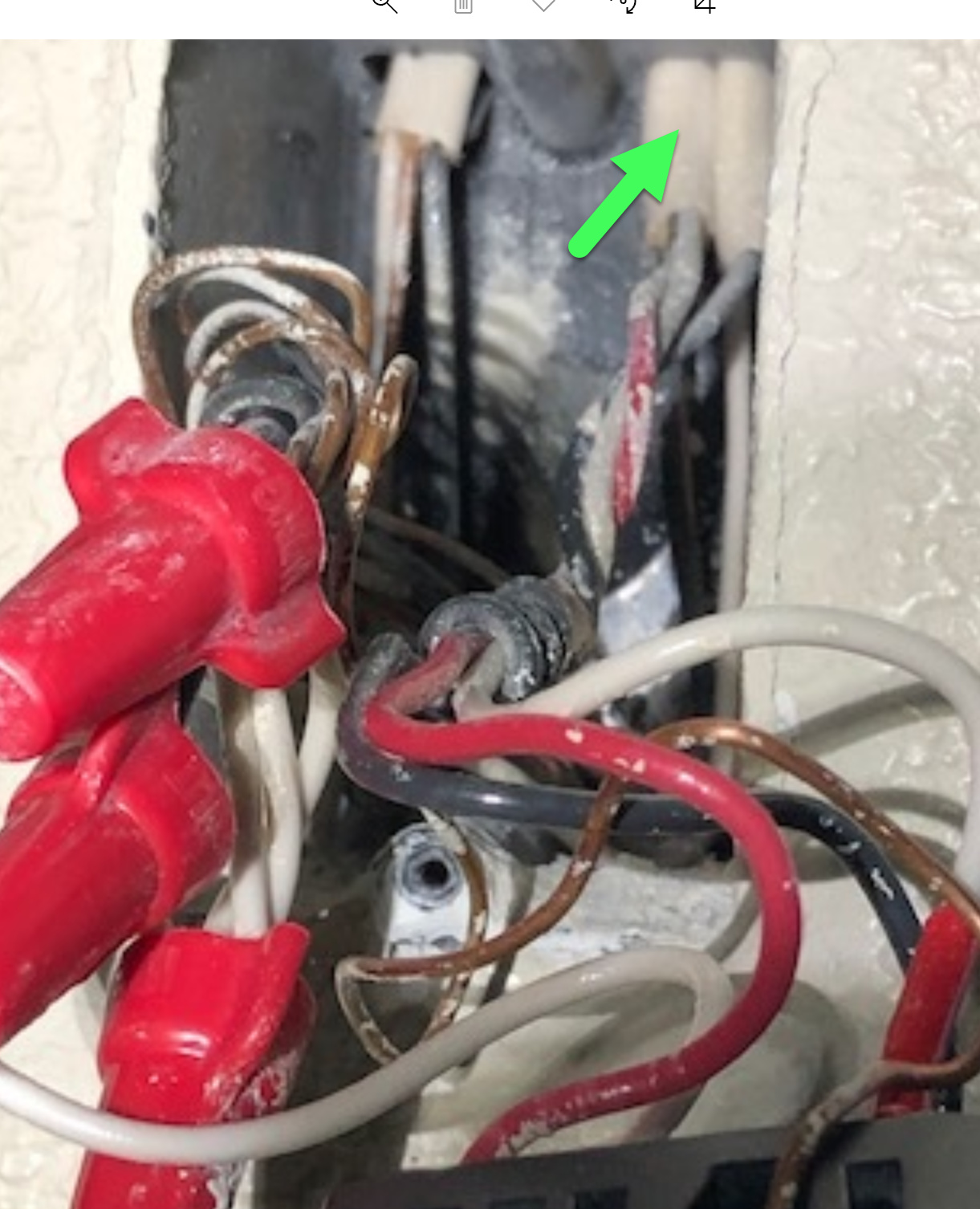
Ok thanks. So just so I absolutely understand, pertaining to the Inovelli switch, the wires presently connected to the Line, Load and Traveler terminals ALL belong to the 3-wire which is the 2nd from the right at the top right of the box? My picture below has an arrow to confirm.
(I’m not concerned about the white connected to the bundle nor the bare ground.)
Asking another way, this means that NONE of the conductors from the far top right Romex nor the top left Romex are connected to the switch. Excluding the bare ground and white connected to the bundle, all 3 wires connected to the switch are from the same 3-wire Romex.
Do I have that right?
Nope not correct. The load(white that has red tape eventually at the switch) and the red traveler come from the 2nd from the right at the top of the box. The Romex at the far right provides the black wire that comes out and then is shown twisted around those two wires from your arrow. And yes none of the wires from the top left Romex are connected to the switch…just connected to the wire nuts in the box
Ok, that’s actually good, maybe . . .
So for terminology, let’s just refer to conductors by colors and Romex by numbers. See my pic below.
Let’s get this mapped out. Please complete:
Romex 1 (2-wire) - Black connected to
Romex 1 (2-wire) - White connected to
Romex 2 (3-wire) - Black connected to
Romex 2 (3-wire) - Red connected to
Romex 2 (3-wire) - White connected to
Sorry this is like pulling teeth but it’s better to take things a step at a time. I’m pretty sure I understand it by I take pains to confirm.

Romex 1 (2-wire) - Black connected to Line Inovelli Dimmer
Romex 1 (2-wire) - White connected to Wire nut with other whites
Romex 2 (3-wire) - Black connected to Wire nut with other blacks
Romex 2 (3-wire) - Red connected to Traveler Inovelli Dimmer
Romex 2 (3-wire) - White connected to Load Inovelli Dimmer(again has red tape at Inovelli side)
And no this isn’t nearly as bad as pulling teeth
Ok thanks. So I was looking for the mapping to understand the configuration, but it just occurred to me that your electrician wired this and it’s not working, so the current mapping may be of limited value. By chance, do you have pictures or a drawing of the dumb switch configuration that was working properly before the Inovelli?
I’m guessing no, so here is where we are.
At the Inovelli box, a 2-wire and a 3-wire are involved with the switch leg. At the far box, a single 3-wire is involved with the switch leg. So that leaves two possibilities schematic wise. Both of these use 3/2 in one box, 3 in the other configuration.
1 - This is a neutral installation with the power being fed to the Inovelli box via the 2-wire
or
2 - This is a non-neutral installation with power being fed to the light.
So I think the key is going to be a test of the 2-wire in the Inovelli box. Remove the black and white connections from the from the 2-wire so that you just have a black and a white not connected to anything (you can leave the bare ground alone).
USING A METER (not a proximity tester), test for 120V on the following:
-
Between the black and the white
-
Between the black and the bare ground bundle
-
Between the white and the bare ground bundle
To be thorough, test with the dumb switch IN BOTH POSITIONS.
Knowing how the voltage comes into this circuit will let us know the configuration.
Sort of related rant: Part of the problem is that your Inovelli switch box also seems to be used as a junction box (the unrelated bundles). Makes me wonder what was going on and what they were thinking. I’m wondering if those additional bundles are on another circuit, SO WHEN YOU ARE IN THAT BOX BE CAREFUL AS THROWING ONE BREAKER MAY NOT KILL ALL THE POWER IN THE BOX. Use a proximity tester to confirm that the ENTIRE box is dead.
More rant - Just so you’re aware, that box is probably overloaded. There are specifications about the number of conductors and devices that can populate a box. It’s based on the cubic inch size of the box. I didn’t do the math but there are a lot of conductors in there.
So I don’t have pictures of before. My guess is wiring of previous dumb and this smart was likely the same. Not sure how I feel about doing all the testing as that stuff is not really in my wheelhouse. I certainly could have my electrician test it but I really wanted to have things figured out to a point before he comes back for a couple projects. As for your related rant, I too am wondering what was going on and what they were thinking. I haven’t been electrocuted yet by throwing the one breaker so I do know at least that all the powers shut off by one breaker. To your more rant, yes indeed a lot of wires in there and pulling out all those wires and pushing back is a pain for sure. Will I do anything about that? Maybe but I didn’t have any issues in the five years of this house and it was new construction so probably not. So the main question I see now is what do I do with the second dumb switch? Seemingly, it seems that if I keep the Inovelli installed versus just giving up and going back to two dumb switches then I need to determine if a second Inovelli Red Series On/Off will work or if I should use an AUX GE or Homeseer? According to what I was told of that switch and shown in one of the pictures, it is a dead three way that does not have a neutral
I understand your quandary. The biggest problem from my end is that if we had a working 3-way with two dumb switches, wired properly, it would be very easy to understand. But unfortunately your electrician made changes and so we don’t know the original configuration.
I’m reasonably sure that I understand your configuration, but I don’t make recommendations based on reasonably, hence the testing. I’ll be glad to coordinate with him as well if you decide to bring him in.
More than likely, you have a non-neutral situation at the Inovelli box. I’m guessing the hot is coming in via the 2-wire black and returned to the light via the white, but only testing will confirm. If that’s the case, then the 3-wire is going to your other box.
In the other box, if you go forward with the installation, you probably need an Aux, because you are probably limited to an Inovelli dimmer, because your probably have a non-neutral.
Shocked. The word you want to use is shocked. The E word means you’re not coming back.