I’m looking for advice on how to wire a 2-1 switch and 2 aux switches in a 4-way configuration where the power source comes from the light.
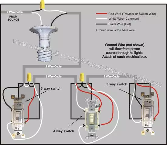
The current non-smart wiring is exactly as pictured here:
In my case, the last box is a 3-gang box, which does have a neutral available (all are on the same breaker circuit). This is where I would prefer to have the 2-1 switch, if there’s any option.
I’ve replaced many single-pole switches with smart switches, and a couple of 3-way ones, but this is my first time setting up an Aux switch and first time having the power source come from the light, so I’m a bit unsure.
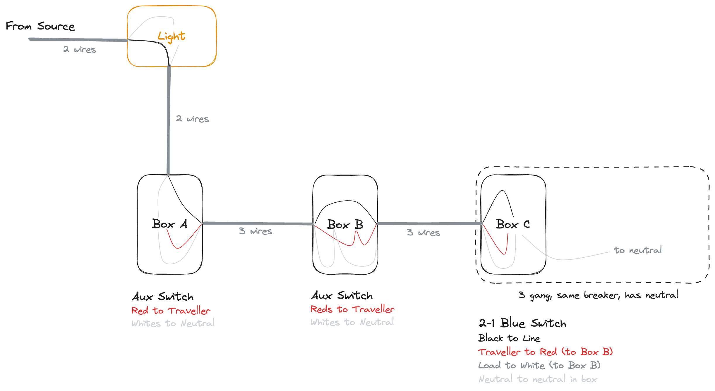
Is this how I should re-wire it to work with the 2-1 switch + aux switches, or am I still missing something?
Yes, that looks correct with the exception of my neutral comments to follow. You’re sending the black hot all the way to the right box and returning it switched to the light via the white. The red conductor is used to connect the travelers.
I am always leery when someone says a neutral in the same box as a non-neutral leg is on the same circuit. If there is a hot and neutral in the far right box, then why doesn’t the leg start there? Anything is possible, but that makes me pause. There are other mis-wirings that can make someone believe that conductors are on the same breakers when they are really not. So I recommend the following:
If you want this to be a neutral installation, I would disconnect the hot/neutral at the light and then send it from the far right box, since you report a hot/neutral there. Connect that hot and neutral from THAT box to the switch. Use the black and white on the 3-wire going to the other boxes to send the switched hot load and the neutral. And the red for the travelers. In this manner you can be certain that you are not borrowing a neutral.
Thanks so much for taking a look and providing feedback. I hadn’t considered sending the hot from Box C here, but that would totally work and would actually end up with a configuration matching what’s suggested in the Inovelli Help Center.
I can appreciate how my description would give you pause. Though, in this case, the “Light” is actually two bedside lamps plugged into a switched outlet. The outlet already has a hot/neutral, so I guess it makes sense that they would run the switches off of it. Sorry, I should have mentioned this in the original post, and I realize that first image isn’t entirely accurate — I was too focused on the wiring of the switches, I forgot to mention the light.
As for the other switches in Box C, they are both single-pole switches for two ceiling lights. They are all definitely on the same circuit as the outlets in this room.
Given that missing info about the outlets, would you still recommend the same thing?
Inovelli switches and smart switches in general should not be used to switch receptacles. When you switch a receptacle, that switch has to be able to handle any potential load, which on a 15A circuit is 15A. Inovelli switches and smart switches generally aren’t rated to carry anywhere near that. In the US, the NEC specifically states that a switch controlling a receptacle has to be able to carry the load of the branch circuit, i.e. the breaker’s capacity. It is for that reason that Inovelli specifically states the 2-1 switches should not be used to control outlets i.e. receptacles.
Plug the wrong thing (like a vacuum) into the wrong outlet on that receptacle and you probably won’t appreciate the loud noise and the smoke.
The proper solution here is to use a smart outlet which is typically designed to carry the proper load. There are several on the market and Inovelli’s is under development . . . Project Jambry. The approach here is to wire the switch with just a hot and neutral making it a scene controller and then use the multi-tap capability to control the outlet.
Oof, I should have known this too, I do remember reading about the reduced load of the switches now that you mention it. Thank you for reminding me. I will scrap this plan.
Ultimately what I want to do is control is two Hue bulbs. Would it be a crazy idea to wire up the 2-1 switch + two aux switches without connecting them to a load, to effectively just use them as a controller? Would they work this way? Then I could just make sure the Hue blubs are always powered. My plan was to use this in smart bulb mode anyway and bind the bulbs to the switch.
Btw, I didn’t know about project Jambry, but that looks like a great product too. Congrats on the recognition there, well deserved!
Interesting idea. The Aux can certainly send scene commands when connected to a 2-1. I’ve not tried it with a no load config, but I’m guessing it would work. If someone has done this and can confirm, that would be great.
You could also use all 2-1’s if you don’t mind the cost and want the LED bar at all three locations.
I didn’t read all the comments but On the original wiring the blue should be in the left box hooked up non-neutral and the hot and traveler get fed to the other boxes for the aux switches.
with live and neutral in the right box you use those and feed neutral, traveler and load to the left. The switched receptacles get the load and neutral from this.
I’ve not tried it with a no load config, but I’m guessing it would work. If someone has done this and can confirm, that would be great.
Update: I wired it up this way yesterday and all is working great. There is constant power going to the Hue bulbs, the 2-1 switch is wired in as a controller with no load connected in Box C, and the two Aux switches are connected via the travellers and working perfectly.
@Bry Appreciate all the advice working through that. Thank you!