Hello,
I’m looking to install a Blue Dimmer (Model #: VZM31-SN) and an Add-On (Aux) Switch (Model #: AUX01) in a non-neutral three way setup. Wiring is a little out dated so specifics are a little unclear. Looking for advice on how best to wire the two switches.
Both boxes appear to have a three wire romex for the traveller wires and two wire romex to the light fixture. This differs a little bit from the schematics presented at Blue Series Dimmer Switch • Wiring Schematics | Inovelli Help Center , where only one box has the two wire romex to the light.
I don’t have any preference on which box the actual dimmer goes in if that helps. I understand how to wire the dimmer switch, but I don’t know how exactly to handle the extra wires that would be in the box that holds the aux.
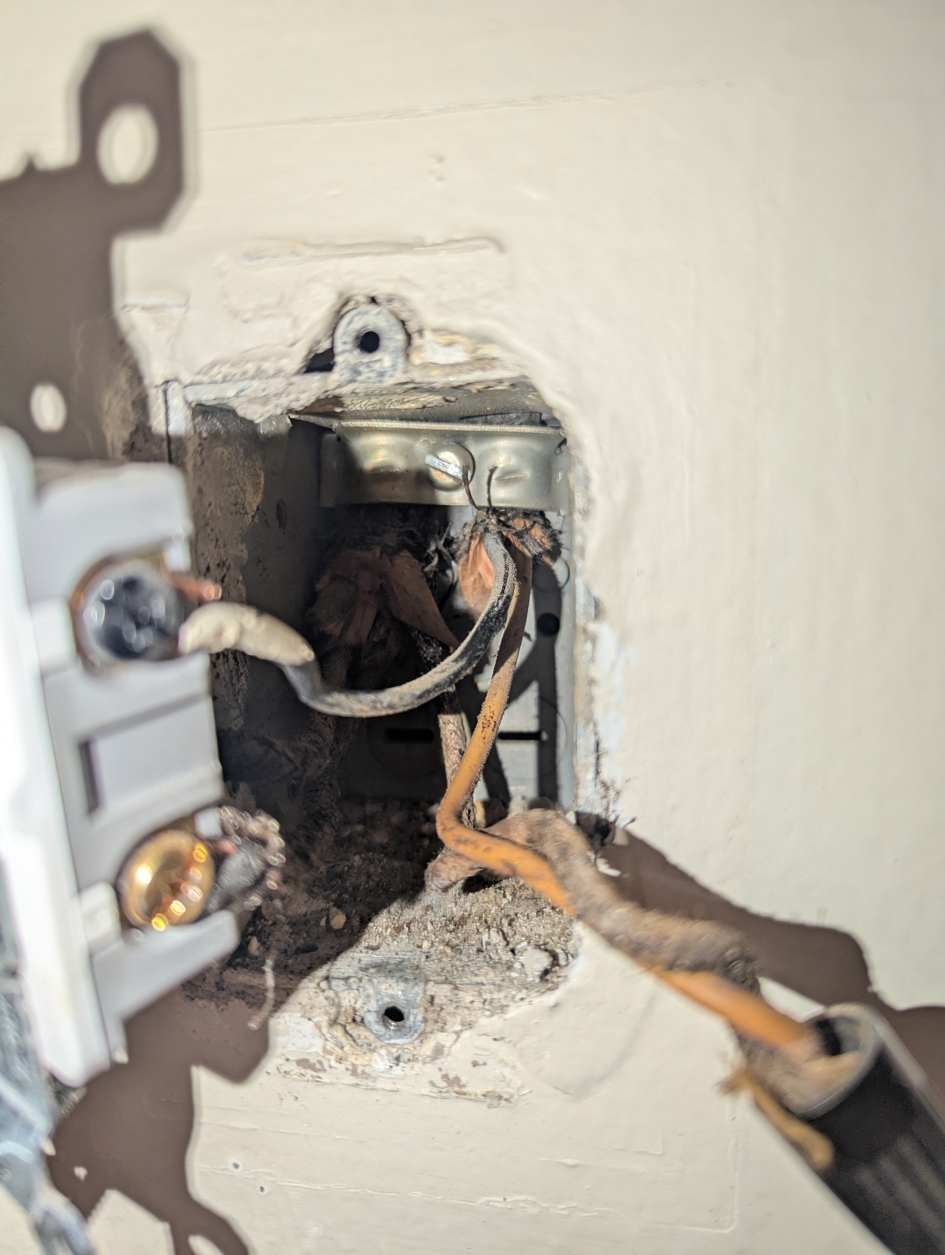
We can call this Box A. In Box A when the light is off, there is voltage on the black screw coming from the two wire bundle and one of the wires into a brass screw from the three wire bundle. In Box A when the light is on, there is voltage in all three wires going into the switch.
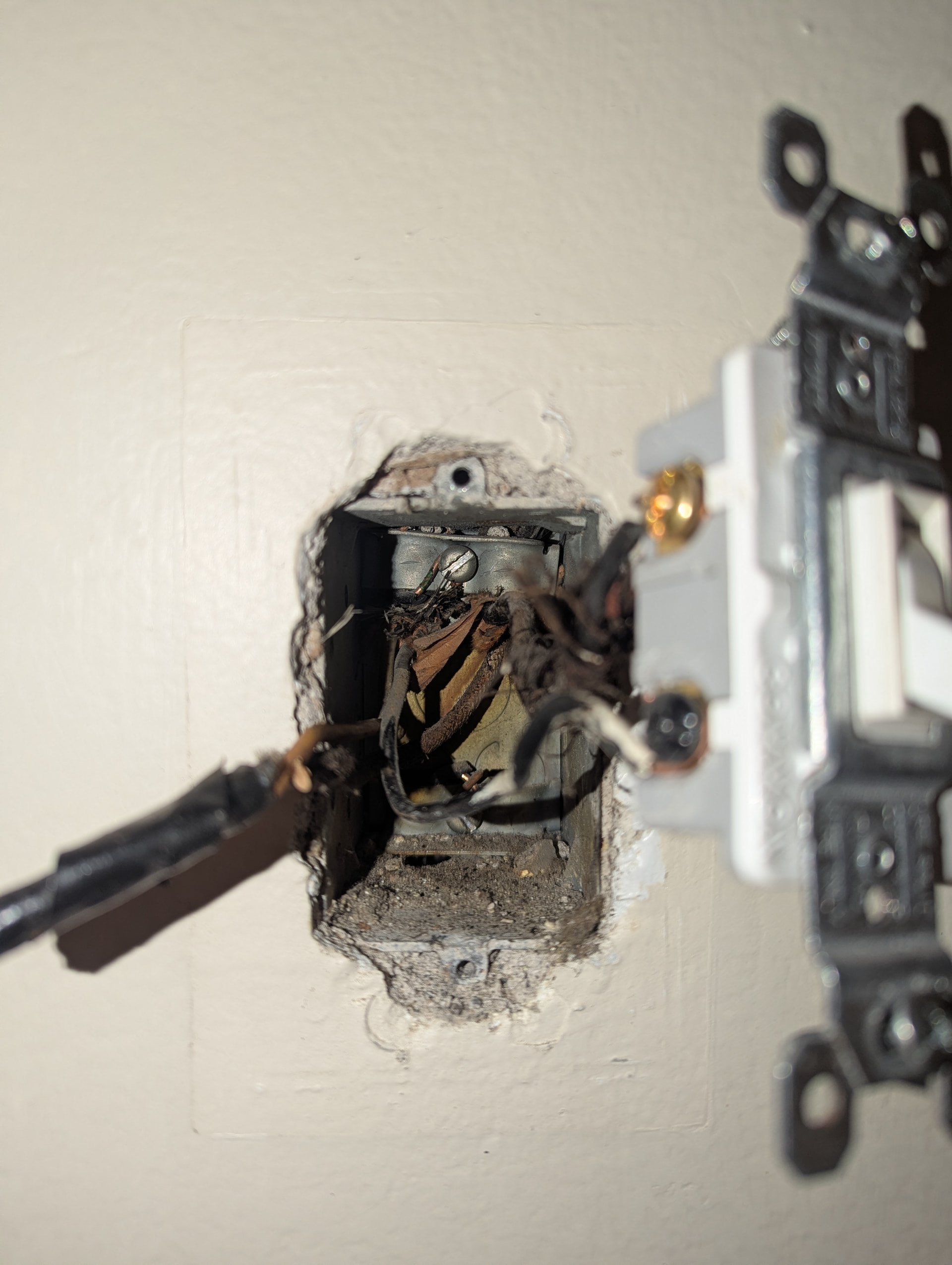
We can call this Box B. In Box B, when the light is off there is only voltage in one of the brass screws from the three wire bundle. When the light is on, there is voltage in the wire from the two wire bundle into the black screw and voltage into one of the two wires from the three wire bundle into the brass screws.
Adding what I think is my current understanding of the wiring
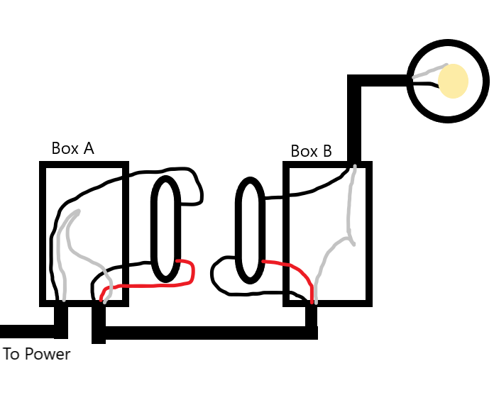
Looking into it a little further, this makes more sense as a neutral setup. Other switches that I’ve done have been non-neutral so I just assumed this was the same. Going to attempt to wire as described in a neutral 3 way setup.
