So I have 3 Blue series switches that were affected by the signal issue and have received my replacements already. Now I know there are some people that were able to repair their original switches and make them ~90% effective again. My question is, is there anyone that was successful in this repair that would be willing to repair mine for a fee?
If this type of discussion is not allowed then please feel free to delete this post.
There may be some hobbyist that’ll do it for me for a fee. Also check to see if you have a local PCB repair shop nearby. They may be able to help you out too.
I think this post has all the info you will need. There is also a video in that thread somewhere that shows how to take apart the switch so that it can be easily reassembled.
Sorry to hijack a thread, but the forum won’t let me start a new one, and all the ones I can find discussing the technical aspects of repairing the faulty zigbee models are closed.
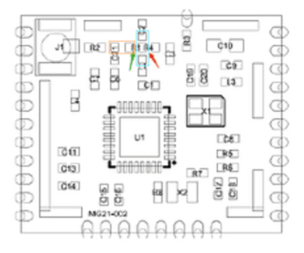
I finally got around to trying to repair my batch of affected switches (I never tried to install or pair most of them). So far, the first 2 I’ve opened and probed with my meter already show full continuity between the areas that I am supposed to solder together. To clarify, I’ll borrow an image from @alabaster3211
The resistor is in the wrong position as expected, but everything in the blue and orange areas already shows continuity between each other with my multimeter. Even going as far out as the far end of R2 on the left and beyond R4 on the right all shows as electrically contiguous before I change anything. Even the Zigbee antenna is contiguous with every pad in that section. I’m having a hard time understanding what a blob of solder is going to do to short a connection that is already connected. I’ve double checked several times that that empty R1 pad is already contiguous with everything around it.
Am I missing something here? Is just removing the bad resistor all I need to do? For what it’s worth I did try pairing one of these switches before opening it, and it paired no problem on a bench test unit. Other than hubitat’s rather limited Zigbee routing table I have no tool to test the zigbee signal, so I don’t know hos strong it’s signal will be. I’m trying to decide if I should crack open my dozen plus other affected switches, or just install them in the new house and wait to see if the network fails.
Also tagging @samuelt83@dahanc as you seem to have some experience from other threads.
The solder jumper is to connect the trace shown in blue to the trace shown in orange. Without this connection little RF energy is transferred from the transceiver chip to the antenna.
Thanks, I’m aware that is the intention, I’m just confused how a blob of solder changes anything when the 2 areas are already electrically contiguous elsewhere. Are we just expanding the connection to lower the overall resistance between the two segments? When I check the resistance between blue and orange I get 4.0ohm, vs 2.2 within each section, or along a bare copper wire (probably mostly from my tiny makeshift probes). Is that what we’re doing here, just subtly decreasing the impedence?
Those nodes are not connected on the RF path if the pi filter inductor is populated in the incorrect position. Any connection you may be measuring is just current leaking through capacitors or other components. You need to measure node to node with a quality multimeter and you should be able to read an ohm or less impedance once it is soldered across the other inductor mounting location. Continuity testing on a meter is not a valid method for checking a circuit like this, as meters show continuity based on current flow and the threshold is not very accurate.