Blue Series Dimming Tech

I remember something similar - in fact I thought in the product name “2-1”, the 2 was supposed to be counting the true (relay based) on/off function plus the dimmer function. The relay was to support CFL & “sensitive” loads. Originally, I think the relay on/off was going to be usable for small motors too (like bathroom fans) - but there were certification issues that stopped it being advertised for this.
I too am now slightly confused about what the relay is doing - the current device handler calls it “relay click” - as if it does nothing more than make a noise. I think I read that this was needed to support multi-way connections with dumb switches. My suspicion is that the true relay functionality got removed to enable more non neutral scenarios (if the relay fully connects the line to the load, then there’s no slight voltage drop available to power the switch!)

3 Likes

It switches the output voltage between the Load and Traveler terminals. This is needed for multi-way wiring. The ‘relay-click’ option was added after the fact as a user request

1 Like

Another chime in here for the sadness that it’s got MOSFETs but not Trailing edge, and the fact that on/off mode isn’t is also not ideal.

I’m used to Insteon, but they had (more or less) 3 SKUs.

Neutral Required Dimmer
Neutral Required On/Off
No-Neutral Dimmer

It looks like trying to cram all 3 of those into 1 SKU has left the product failing at 2 of the 3. You’re like 95% of the way there hardware wise by choosing MOSFETs, it’s quite boggling that they only run forward.

Like others said, I would pay any amount of money for trailing edge dimming, along with real on/off (doesn’t need to be the same SKU)

Please make gen2 of these switches support trailing edge dimming, and either remove the relay or make it actually bypass the dimmers.

3 Likes

The circuit path for a single pole device goes Line → MOSFETS → relay → Load terminal
When the relay is energized (switch turned off) it goes Line → MOSFETS → relay → traveler terminal

Since the traveler terminal is not used in single pole wiring, the relay click completely disconnects the MOSFETS from the load when the switch is turned off.

Thanks! This is the first description that I understood (not that there might not be others out there!).

Under what conditions does the relay have to be enabled? I prefer to have it disabled (i.e.: no click). If I understand it should be enabled when using dumb switches and is not needed to be enabled when using multiple smart switches in a n-way installation.

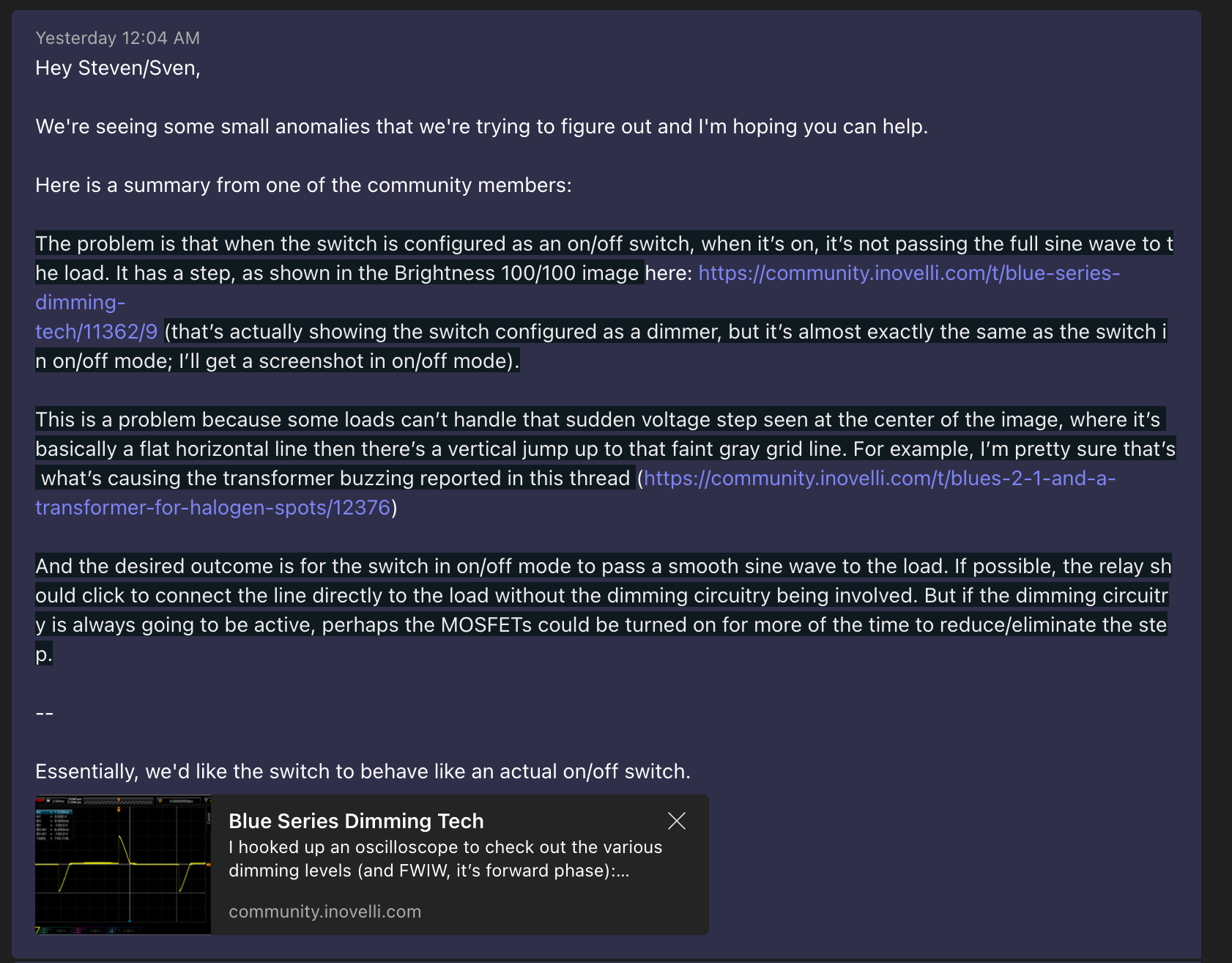
Following up here as we received a response from the manufacturer and I’d love to get your opinion on it since you’ve graciously taken time out to analyze the switches with an oscilloscope and explained to me why this is important.


I’m not sure if this passes the sniff test with you, but thought I’d just throw it out there and see what you think.

Regarding leading vs trailing edge – do you guys think this can be solved via firmware or will it have to be a hardware implementation?

Edit: Actually we got a response around why leading edge was chosen:

“In neutral mode, auxiliary switches and dumb switches are detected. In non-neutral mode, the auxiliary switch is detected. In addition, the detection of alternating current crossing zero. On these detections, leading edge dimming is better than trailing edge dimming.”

4 Likes

In addition to single pole it should also work with 2 (or more) blues bound together since it doesn’t use the normal 3-way circuit logic

1 Like

I’m not an electronics engineer; I think I’d call myself an intermediate hobbyist, amd I’m not really knowledgeable about the details of dimmer switches. In particular, I get the general concept of how the switch works in non-neutral mode, but definitely don’t know the specifics of what limitations that introduces. But in my mostly-uneducated opinion, what he’s saying sounds reasonable to me.

2 Likes

I’m surprised they are using the dimming mosfets for zero cross detection. I’ve mostly seen dedicated/isolated circuitry for that. Perhaps theress no room/cost of components, but then you’re free to use trailing edge dimming.

So the relay is energized the entire time the switch/load is turned off? Seems backwards, but i guess relays can fail in either position.

It only has to operate for dumb switches. You don’t really enable it for dumb switches, when you select 3-way with a dumb switch mode it starts operating because it has to.

1 Like

Well, the switch doesn’t click when you turn power on, right? It makes sense for the relay to only be on in dumb 3-way mode when the traveler is in use. That would keep it off in 1-pole mode and aux switch mode so off in most modes. The click was added just so you could hear a click when you turned it on or off. Well, it might keep the MOSFETs turned-on so the relay click immediately connects the MOSFETs to the load. That part can’t be determined from looking at output waveforms.

Not sure, I’ve not installed mine yet! :slight_smile: They were slated for ballast loads and plans changed once I started reading that it wasn’t what I remembered.

The relay swaps the MOSFETs output from being connected to the load terminal to the traveler terminal. For the dumb three way the AC has to swap terminals to work but for a single way installation that is optional as the MOSFETs are used to interrupt the AC so it is not required to switch it from the Load to Traveler terminal. Ideally the design would have had a second relay that bypasses the MOSFETs for ON/OFF operation but it seems there was not enough room.

1 Like

It is energized because that is the state for the incoming AC to be passed from the Line to Traveler and not Line to Load.

Ya, kind of exactly like the explanation I posted first in this thread describing what the relay does. You’re not telling me anything I don’t already know.

Honestly the more I see how these devices work the more I really wish it was multiple SKUs

People who are buying HA gear typically don’t want or care that the other switch in a 3 way needs to be smart.

Get rid of the relay (or make the relay actually bypass the MOSFET’s), use the traveler for communication, this can still work in dumb mode but it means the smart switch has to be at the load wiring. There is no reason you need to be switching line power to/from the traveler.

3 Likes

For an on-off switch, to me it should

  • require a neutral
  • have a physical or solid-state relay with pure sine wave output

For dimmers, I always buy the neutral version (if available) as my locations all have it. Dimming seems to just work better with one.

I hope the next series of Blue products have the same SKU as the Red series did.

3 Likes

For an on-off switch I’d actually prefer the simplicity and increased current carrying capacity of a relay.

3 Likes

Just chiming in to add that I’ve been really disappointed with the dimming tech. I’ve installed 20 dimmers and nearly every one has flickering issues when dimmed - across at least ~7 different fixture types all with explicitly-dimmable LED bulbs. Really hoping something can be done at the firmware level vs requiring a new SKU+buying new switches.

2 Likes