There is a 3 wire cable going in between the two boxes, containing the two travelers and a common wire.
Downstairs, the common wire is live and feeding the circuit but we need to change this in the upstairs box.
Upstairs, you need to find where that black wire from the 3 wire cable connects, attach a pigtail to that to feed the smart switch upstairs.
Your “blue” wire is currently just a traveler, but needs to be repurposed as a neutral… If you grab a paper towel and put some rubbing alcohol on it, you can remove the blue marker so it goes back to its original color of white.
And while it shouldn’t NEED to be said, you should be doing this with the power turned off at the breaker for that circuit.
Ok, that makes sense. I previously had the light working with the smart switch, but the smart switch was installed downstairs and upstairs I tied the blue and black wires together. I disconnected this because I assumed it was back feeding and unsafe.
I’ll clean the wire tomorrow and look to see how I can feed the power upstairs.
I’ll see if I can come up with a image trying to explain what needs to be done. If you’re not going to continue messing with it for now, it should give me a bit of time to get something made up for you.
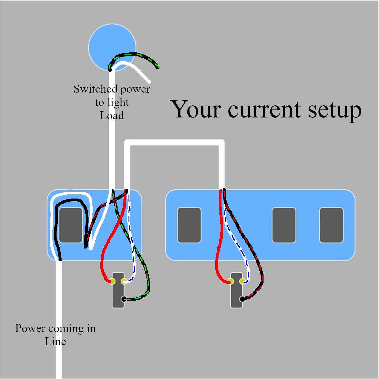
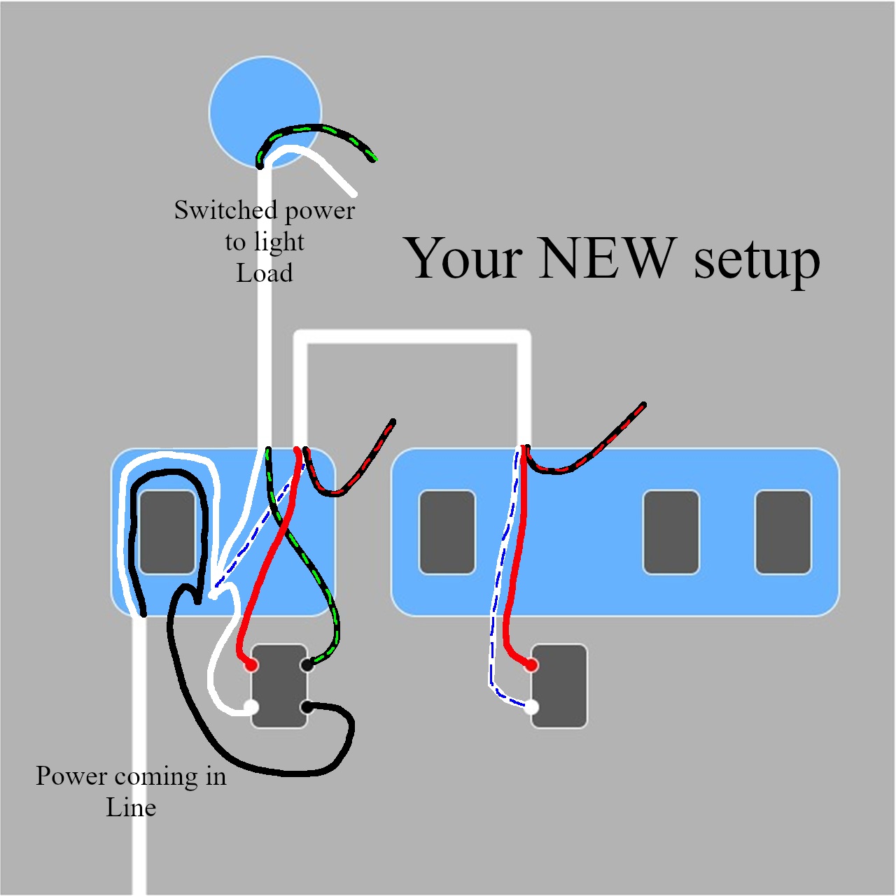
Here you go, hopefully this makes things clearer… provided you with both how it/was is currently wired as well as what you need to change it to. I did not include all of the extra wiring, only the wiring specific to your switches.
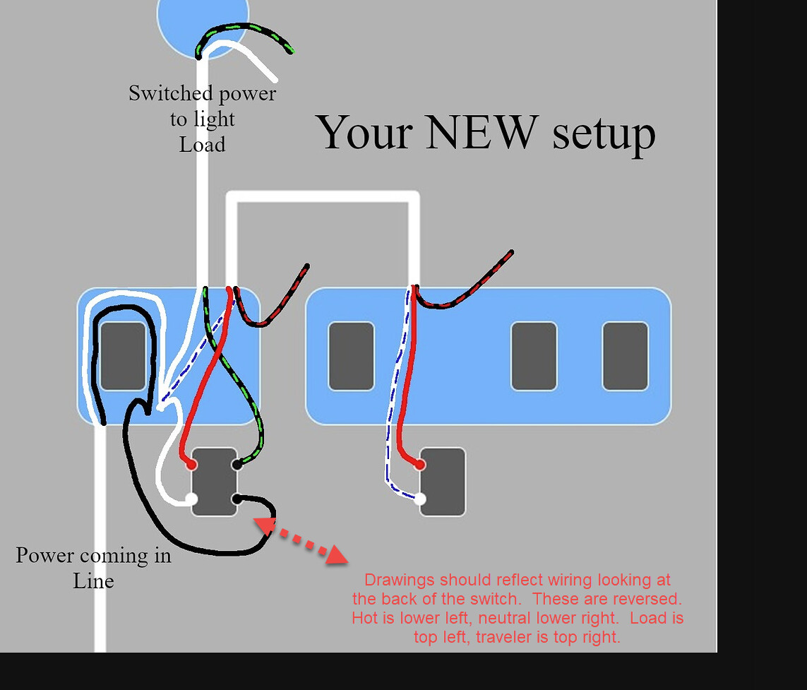
Drawings should always reflect looking at the BACK of the switch to avoid confusion. In the NEW setup drawing above, the connections are reversed, drawn as if you are looking at the front of the switch.
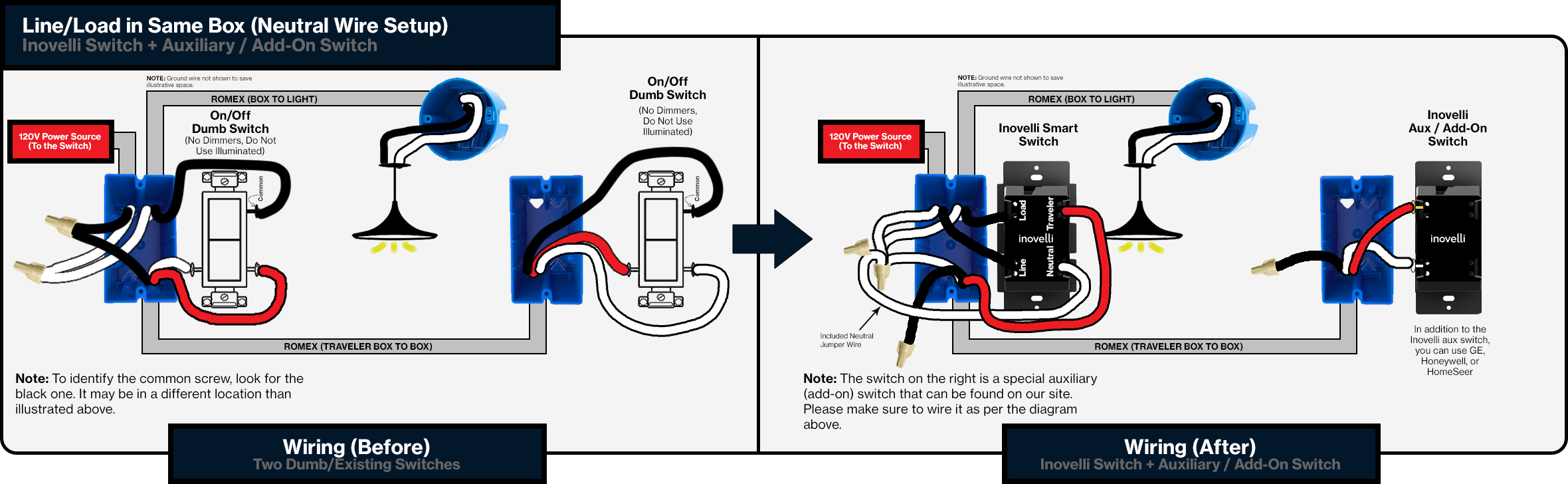
I haven’t confirmed the wiring topology, however, if the solution is correct, here is the proper Inovelli drawing. It’s always best to rely on Inovelli drawings if available.
While I feel it’s pointless to argue over whether drawings should reflect looking at the back or front, so long as they’re properly labeled it shouldn’t matter. As you can see, in the “new” diagram the switches are color coded, and this shouldn’t matter.
The only issue with any company’s supplied drawings is that they can never include all the wiring already in the boxes or which side of the boxes that the wire enters (which seems to cause the most confusion when I am assisting, mainly on Reddit). I’m not saying that mine here is any better in that regard, but hopefully as easy to follow.
As a 20+ year electrician, while I can’t say I’m the greatest with creating visual diagrams on a computer, the one I supplied matches the one you linked for all practical purposes and is correct.
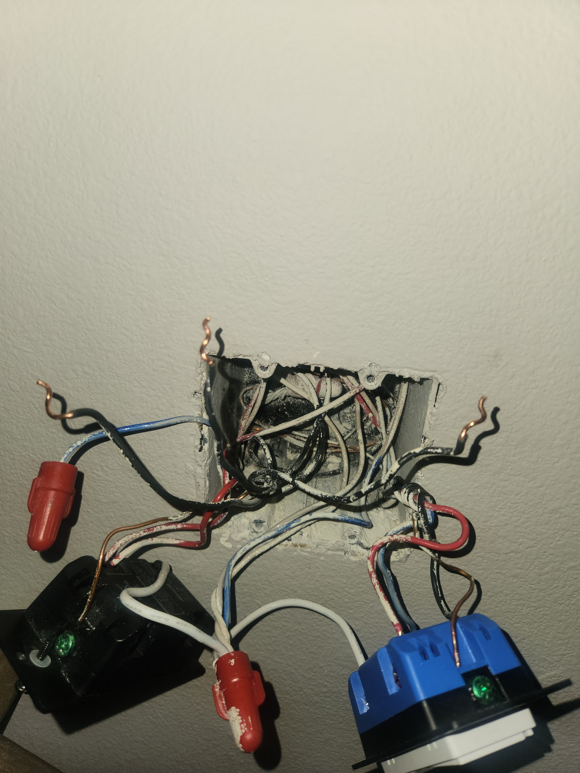
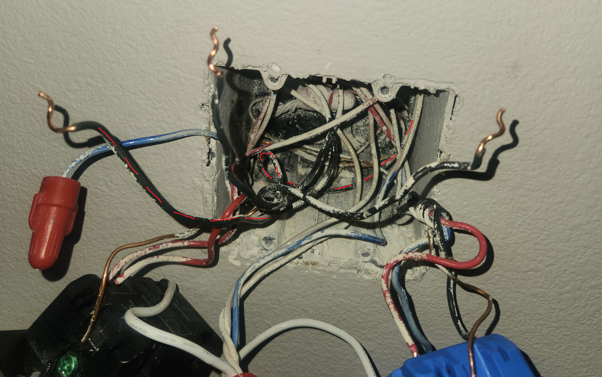
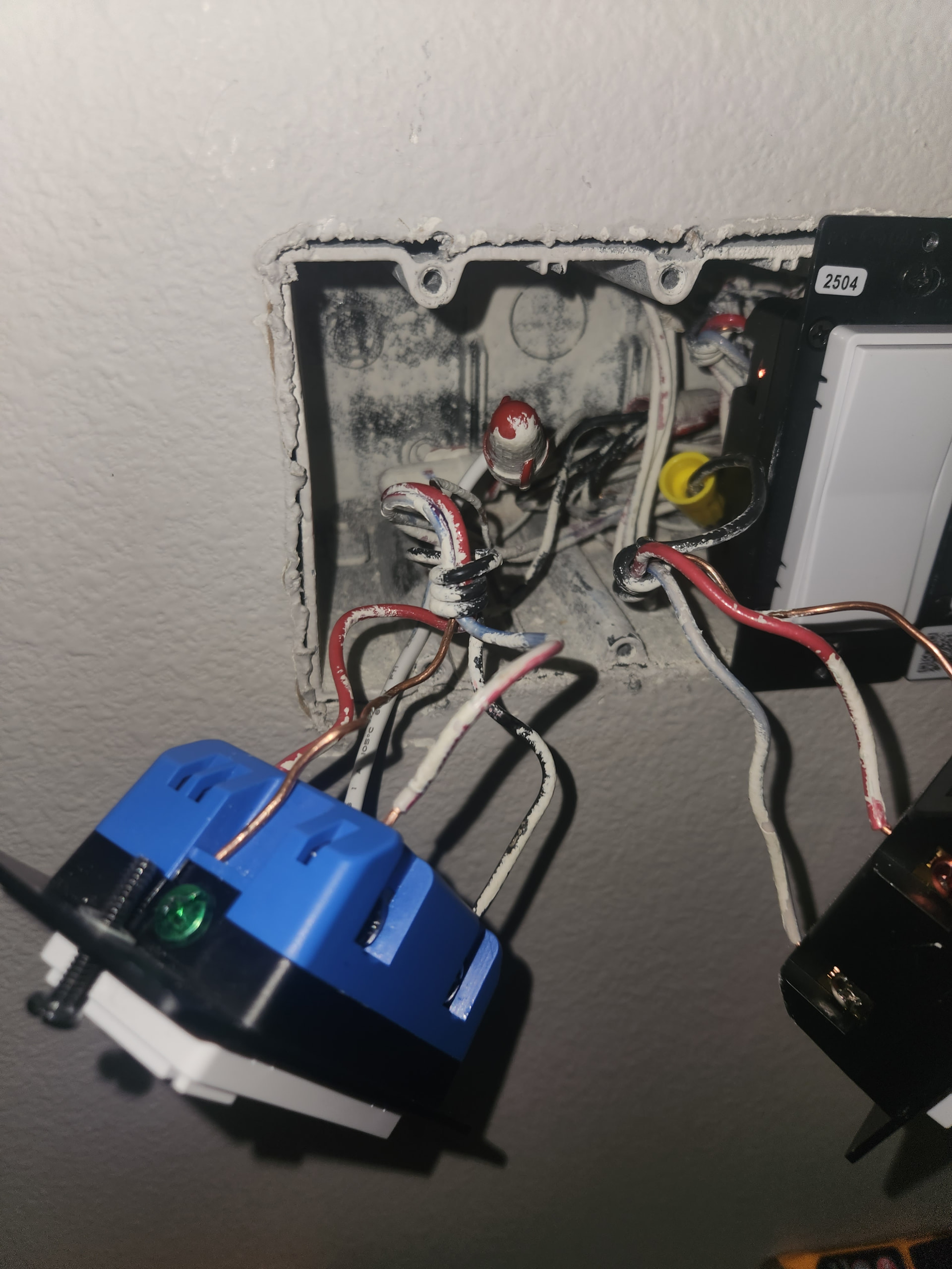
@koadic the black wire in the middle is the live wire. My only question now is due to there being two other black wires bundled with that wire. One will go to the downstairs and be capped off. The other one is my concern. I’m assuming they were feeding something else with that wire. Does this change how I should wire this?
I tried marking the one going to the other box, from what I could determine in the photo… That black wire (marked with red dashes) can be capped off, but the other two need to be reconnected, along with a pigtail, which is just a short piece of wire to go from the connection under the wire nut to your switch… just like the white pigtail that they supply in the box for connecting to the neutral.
If you needed to, you could probably cut a portion off of the black wire going downstairs, but that is a “destructive” solution and can’t be undone once you do it. If you have any spare wire sitting around, that would be a better alternative.
I guess, technically, the Inovelli switch can accommodate 2 wires in the Live connection, so you could just take both wires to the switch, but I think it is better practice to add a pigtail instead.
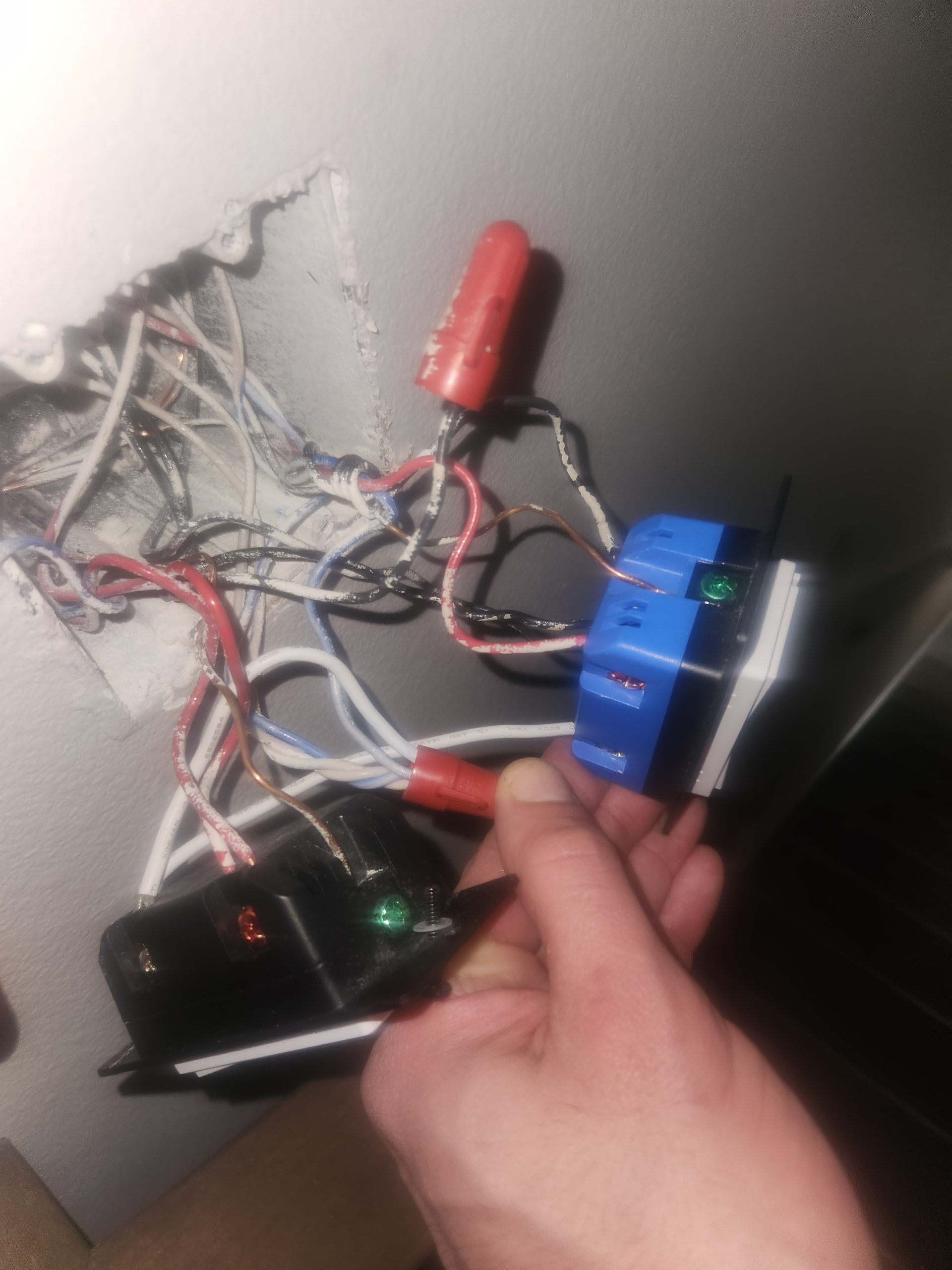
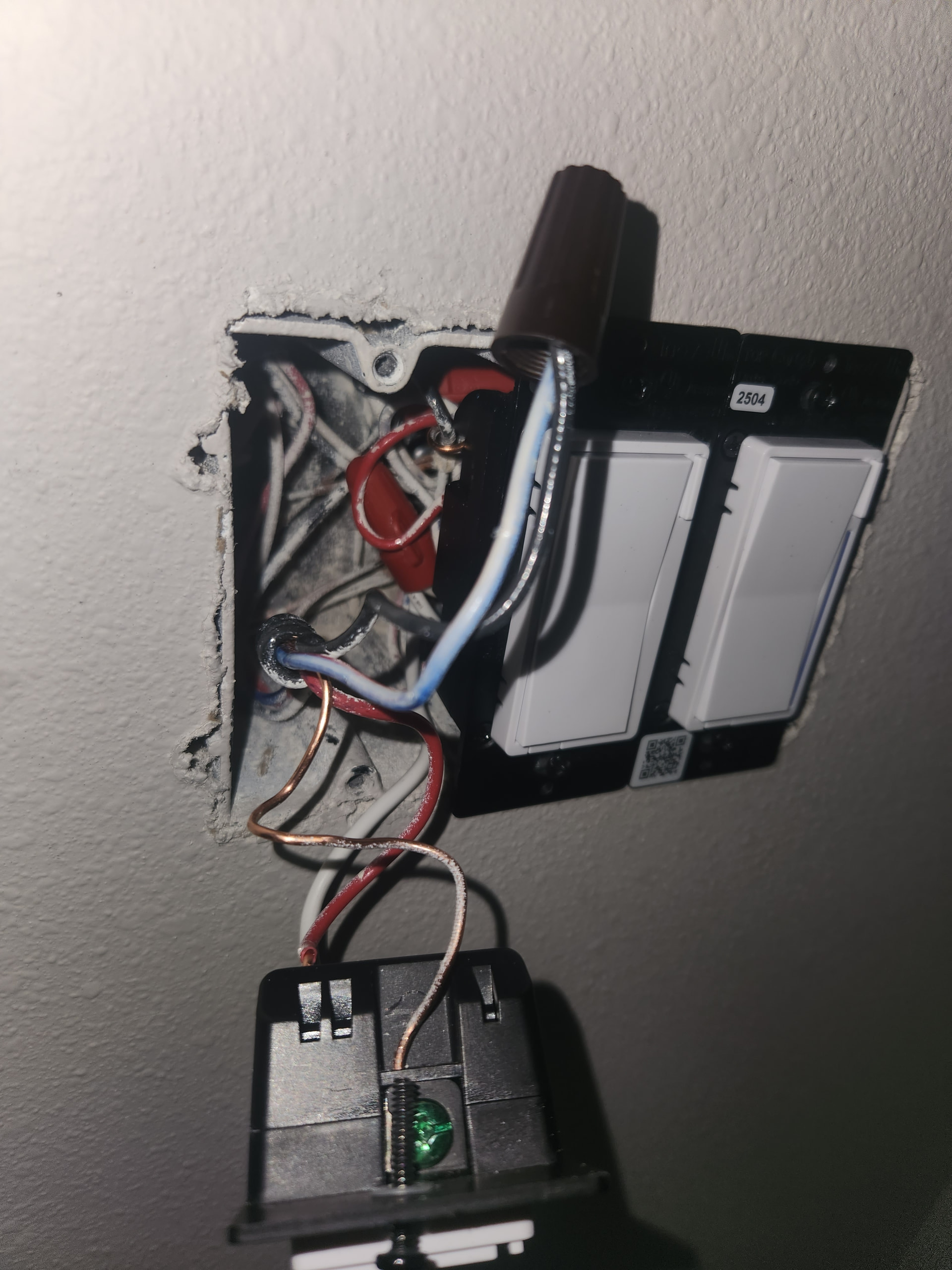
@koadic I just confirmed that the one on the right in the picture goes to the downstairs switches. I tied the live with each on separately and tested the downstairs. I’m assuming I should plug the middle and the left into the smart switch. I’m assuming the one on the left is feeding something else. Let me know your thoughts.
You really should run the wire to the wire nut, not to the other switch…
Electrically, it’s all connected and fine, but should you ever need to service or remove the switch on the left, then your new switch may lose its neutral connection.
If the bundle is too big, it would be better to run the neutral pigtail from the switch to the wire nut, and run the repurposed traveler to your new switch instead of the wire nut… so there are two neutral connections on the new switch and not the existing switch. This way, both neutrals connected to the new switch are for the same switch circuit as well… there is no issue losing the neutral to the new Aux switch if servicing the new main switch
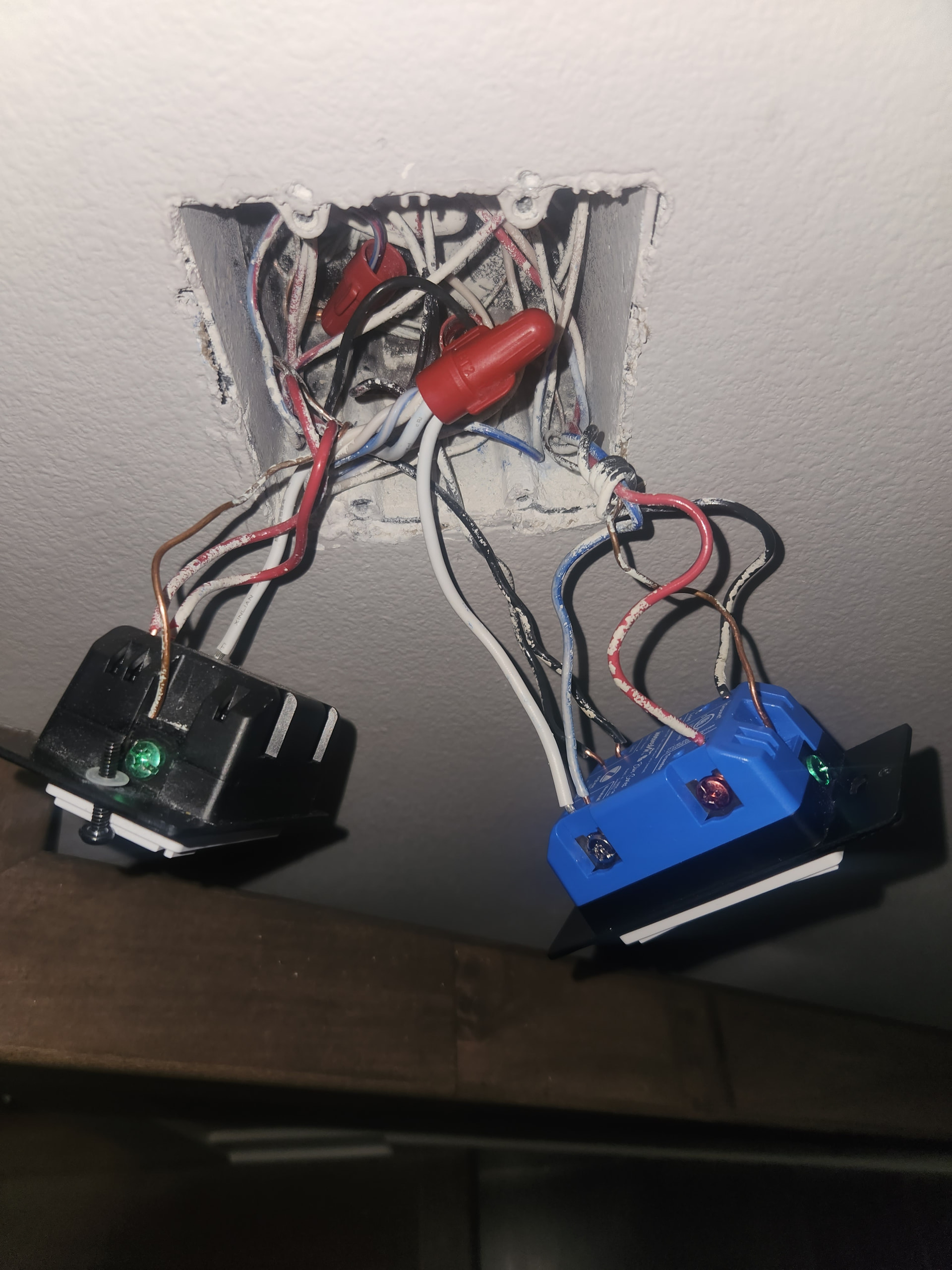
@koadic can I have you look at one more? The other one works great! Thanks for your help. It’s another 3-way switch. I spoke to my electrician when he was here today and I asked and he said it was ok, but said he doesn’t know much about smart switches.
Black on the 4 gang box is tiesd to the only live bundle. Blue and red wire is acting as my load wire. Tied into the neutral bundlein each box. The other 3 gang box does not have any live bundles. I had to tie the second travler wire to the switch leg wire to get the light to work. Is there any issues with this?
From the pictures, I would suggest a couple changes, but I’d need you to check a couple things for me first before I provide any kind of answer… just to make sure
In the first picture, the 4 gang box, you state that the black wire connected to Live on the switch is connected to the live bundle… You should find the other black wire from the 3 wire cable going to the 3 gang box and find the Load wire it is connected to.
Provided that the Load is in the same box as the Live, I would tell you connect the Load directly to the Dimmer where you currently have the “white” wire, and to repurpose the “white” traveler as a neutral to your Aux switch. Then the black going in between the boxes can be capped…
I suggest this because you are currently utilizing a neutral from the 3 gang box, but sometimes lighting circuits are split up and you would need to verify that what you are tied into is on the same circuit. Even if it is, it is a more “tidy” installation to bring it down from the 4 gang box over one of the old travelers…
Just like the other one, you can tie the “white” into the Neutral on the Dimmer, and connect the Aux switch to the red Traveler and the “white” neutral, disconnecting from other neutrals in the 3 gang box.
EDIT: If you can verify that the Neutral you in the 3 gang box is connected to is part of the same circuit as the one in the 4 gang box, then what you currently have is technically fine and will work, it just isn’t how I would do it.
So I hooked everything up and missed the neutral in the 4 gang box. Connected the neutral only in the 3 gang box. The lights were on permanently, but half power. Once I hooked up the neutral in the 4 gang box everything worked fine.
I already confirmed that the live wire is in the 4 gang box.
If I wire it the way you described first, I wouldn’t have a load wire (blue/red). Or am I thinking about this wrong? I know red is always travler in my house. So that leaves the blue red/wire to be a load wire.
In the 4 gang box, disregarding wiring for other lights, you have power in, load out to the light, and a 3 wire cable going to the 3 gang box. Right now, you have the load going to the 3 gang box over the “white” wire from the 3 wire cable and then back again to the 4 gang box over the black from the 3 wire cable… which is then connected to the actual Load wire.
What I am saying is that in the 4 gang box, you can find where the Load wire and the black wire from the 3 wire cable are connected, disconnect them, and connect the Load directly to the switch instead of repurposing 2 of the 3 wires in the 3 wire cable to take the load from one box to the other and back again.
Then, in the 3 wire cable going between boxes, you could use the red for Traveler, the “white” for Neutral and cap off the black, so you then have a known good neutral going down to the Aux switch instead of using the neutral in the box which “might” be from a different circuit.
If the neutral is for a different circuit, then that is no good… but if that circuit is the same as the one in the other box, then it’s technically fine.